background image


5

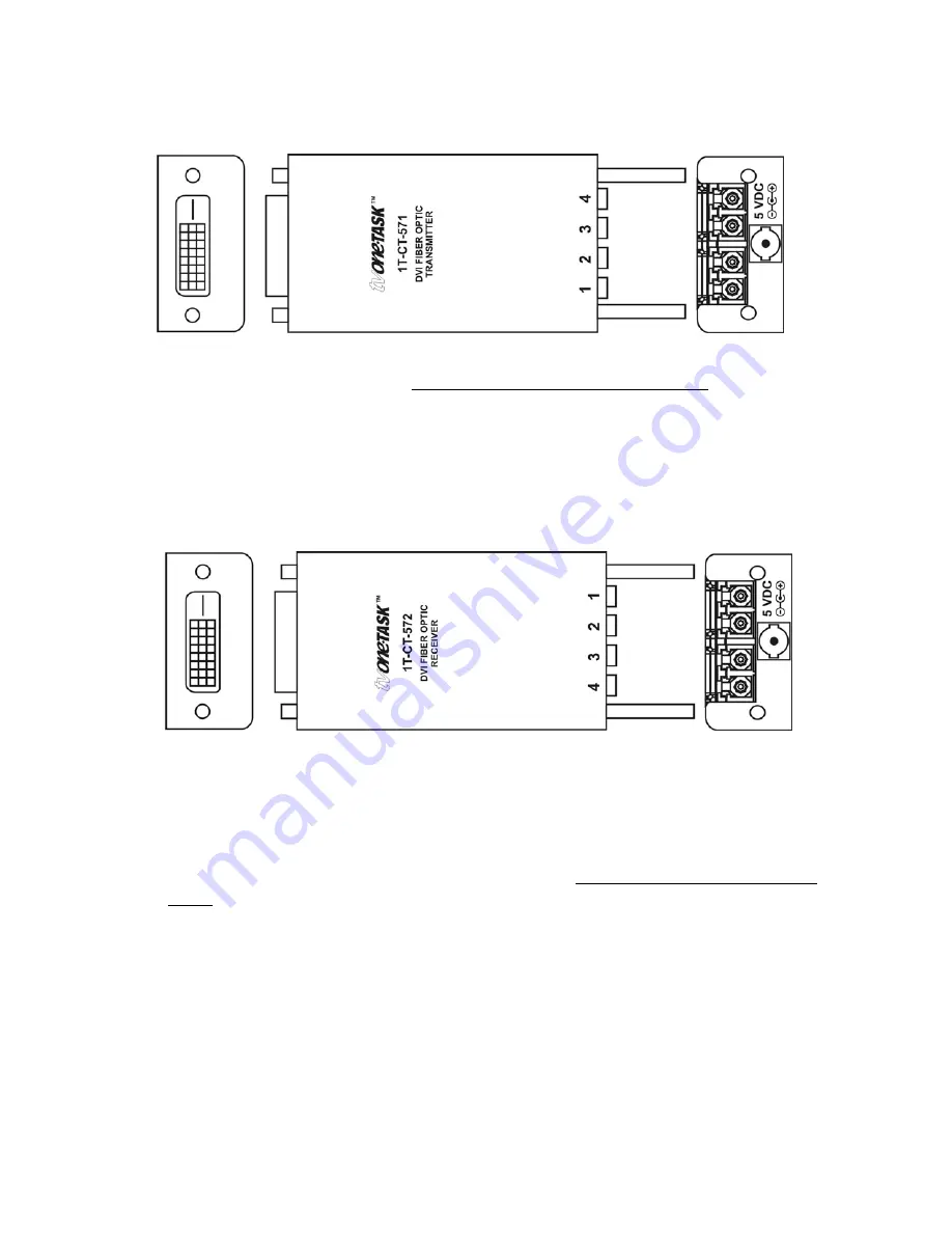
4.2 1T-CT-571 

Transmitter 


1.  Connect the source device’s video output directly and securely to the DVI IN 

connector of the Transmitter. DO NOT use an intermediate cable.   

2.  Connect 4 ea. Fiber Optic cables to the type 4-LC connectors on the 

Transmitter.* 


* It is recommended that you label each Fiber Optic cable at both ends so that you 
can be certain of connecting them correctly.  

 
4.2 1T-CT-572 

Receiver 


1.  At the remote location, connect the other end of the Fiber Optic cables to the 

type 4-LC connectors on the Receiver. (Make certain that cable 1 is attached to 
the cable 1 connector on both ends and each of the remaining cables is attached 
to the same numerical connector on both ends,) 

2.  Connect the DVI OUT connector of the Receiver directly and securely to the 

video input of the remote display or other device. DO NOT use an intermediate 
cable.  

3.  Connect the DC power supply to the Receiver and then to the AC outlet.*  
4.  Turn on the source device and remote display. The source signal should now 

appear on the remotely located display. If not, consult the Troubleshooting 
section of this manual. 
 

*The PC should be capable of supplying power to the Transmitter via the DVI-D 
connector. For this reason, do not connect the Transmitter’s DC power supply initially. If 
the system does not function properly, you should connect an external power supply to 
the Transmitter as explained in the next section.  

Summary of Contents for 1T-CT-570 Series

Page 1: ...Instruction Manual 1T CT 570 Series Fiber Optic DVI Extender...

Page 2: ......

Page 3: ...Introduction 2 2 0 Specifications 3 3 0 Checking Package Contents 4 4 0 Connecting The Hardware 4 5 0 Operating The Unit 6 6 0 Troubleshooting 6 7 0 Limited Warranty 6 8 0 Regulatory Compliance 7 9 0...

Page 4: ...ts and that it is installed correctly All rights reserved No parts of this manual may be reproduced or transmitted by any form or means electronic or mechanical including photocopying recording or by...

Page 5: ...W D 1T CT 571 572 19 6x40x90mm 0 77 x1 6 x3 5 Ea Weight 1T CT 571 572 65g 0 14 Lbs Ea Power Requirement Each Unit Ext PS 5 VDC 1A Environmental Operating Temperature 10 to 50 C 14 to 122 F Operating H...

Page 6: ...KAGE CONTENTS Before attempting to use this unit please check the packaging and make certain the following items are contained in the shipping carton 1x Transmitter 1x Receiver unit 2x Power Adapters...

Page 7: ...nd each of the remaining cables is attached to the same numerical connector on both ends 2 Connect the DVI OUT connector of the Receiver directly and securely to the video input of the remote display...

Page 8: ...nable to assist you contact TV One via our support website http tvone crmdesk com Create a technical support request on the site and our support team will respond within a short period of time 7 0 LIM...

Page 9: ...f TV One with respect to any defective products will be limited to the repair or replacement of such products In no event shall TV One be responsible or liable for any damage arising from the use of s...

Page 10: ...One Latin America 6991 NW 82 Avenue 8 Miami FL 33166 USA Tel 305 396 6275 Fax 305 418 9306 sales latinoamerica tvone com www tvonela com TV One Mercosur Honduras 5849 2nd Floor Office C C1414BNI Capi...

Reviews: