background image

Multi F

orma

t L

CD M

onit

or 

2

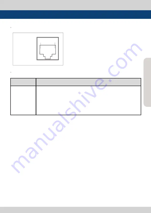
REMOTE (RJ-45)

1: Pin1

2: Pin2

3: Pin3

4: Pin4

5: Pin5

6: Pin6

7: Pin7

8: GND

1

8

Menu Contents


The pin positions are as follows : 


The selectable functions are as follows :

Menu

Classification

Settable Values

PIN 1~6

NONE, ANALOG CHANNEL, DIGITAL A CHANNEL, DIGITAL B CHANNEL,  
PBP CHANNEL, TALLY R, TALLY G, TALLY Y, UNDER SCAN, 1:1 SCAN, ASPECT,
H/V DELAY, BLUE ONLY, MONO, 16:9 MARKER, 4:3 MARKER,  4:3 ON AIR MARKER, 
15:9 MARKER, 14:9 MARKER, 13:9 MARKER, 1.85:1 MARKER, 2.35:1 MARKER, 
1.85:1&4:3 MARKER, CENTER MARKER, SAFETY AREA 80%, SAFETY AREA 85%,
SAFETY AREA 88%, SAFETY AREA 90%, SAFETY AREA 93%, SAFETY AREA 100%, 
708, 608(LINE 21), 608(ANC), DYNAMIC-UMD

Summary of Contents for LEM-150

Page 1: ...Multi Format AMOLED Monitors Operation Manual LEM Series LEM 150 multi ...

Page 2: ......

Page 3: ...to radio communications Operation of this equipment in a residential to correct the interference at his own expense CAUTION Change or modifications not expressly approved by the manufacturer responsible for compliance could void the user s authority to operate the equipment Disposal of Old Electrical Electronic Equipment Applicable in the European Union and other European countries with separate c...

Page 4: ... can cause electric shock and or short internal parts For the same reason do not spill water or liquid on the product Do not attempt to service the product yourself Removing covers can expose you to high voltage and other dangerous conditions Utilize a qualified electronics service specialist for all repairs If any of the following conditions occurs unplug the power cord from the AC outlet and req...

Page 5: ...s in the cabinet are designed for ventilation Do not cover or block these vents and openings since insufficient ventilation can cause overheating and or shorten the life of the product Do not place the product in an enclosed place such as a bookcase or rack unless proper ventilation is provided or the manufacturer s instructions are followed The OLED panel used in this product is made of glass The...

Page 6: ... the static image 30 minutes or image with fixed logos Static images can be remained permanently on the screen Static images Logos captions on screen menu or computer screen Also long term use of 4 3 screen can also result burn in of the screen boundary area This condition is similar to the third party products and not subject to exchange or refund To prevent the image sticking this product darken...

Page 7: ...dcast standards All in one type system Slim and all in one type monitor that requires no other accessories and optimized for space utilization Wide Screen Support This product supports native 16 9 aspect ratio AC DC compatible This product may be powered by a normal AC source but is also compatible with 12 24V DC Remote control function Remote is controlled simply with a cable connection without a...

Page 8: ...s Dual link YCbCr RGB 4 4 4 and YCbCr 4 2 2 formats 3G support Supports 3G A B formats Additional features Loop through out SDI VESA Mounting user interface and rack mountable Active Format Description AFD Supports meta data flags to set aspect ratio and active picture characteristics ...

Page 9: ...ROMA CONTRAST VOLUME POWER ANALOG SDI A SDI B PBP F2 ENTER DOWN UP MENU BLUE ONLY MONO H V DELAY F3 F1 RS232 CVBS1 Y G S Y DVI I SDI IN A SDI OUT A SDI IN B SDI OUT B HDMI CVBS2 Pb B CVBS3 Pr R S C AUDIO OUT AUDIO IN REMOTE RS422 OUT RS422 IN USB ETHERNET AC IN POWER S W DC IN MARKER SCAN ͲͽͽΊ INPUT STATUS ...

Page 10: ...ch of the PBP screens turns on SDI A Button Lamp Used to select SDI A input SDI B Button Lamp Used to select SDI B input F1 F2 F3 Button Lamp Used to activate the function which is set in the OSD Menu SYSTEM F1 MAPPING F2 MAPPING F3 MAPPING After activation adjust the function by using UP DOWN key See section Menu Contents 9 SYSTEM Page for more information SCAN Button Lamp Used to change the scan...

Page 11: ...VI ANALOG DVI DIGITAL and HDMI modes Press the button again to activate the Focus Assist mode which will indicate the edges of the display in the color that can be selected in the WAVEFORM menu MENU Button Used to activate deactivate OSD Menu DOWN UP Button Used to select Main menu and submenu Use UP DOWN keys to select and proceed through various functions ENTER Button Used to enter to submenu an...

Page 12: ...A knob Used to adjust the saturation of the image Control value range 50 50 Unavailable in RGB DVI ANALOG DVI DIGITAL and HDMI modes CONTRAST knob Used to adjust the contrast Control value range 100 100 VOLUME knob Used to adjust the volume for internal speaker and external output Control value range 0 30 Controls Indicators and Connections ...

Page 13: ... BNC Signal input terminal used to feed the monitor COMPOSITE 1 S VIDEO Y COMPONENT Y and RGB G signals CVSBS2 Pb B BNC Signal input terminal used to feed the monitor COMPOSITE 2 RGB B and COMPONENT Pb signals CVSBS3 Pr R S C BNC Signal input terminal used to feed the monitor COMPOSITE 3 S VIDEO C COMPONENT Pr and RGB R signals SDI IN A BNC HD SD SDI signal input terminal for SDI A SDI OUT A BNC H...

Page 14: ...2V 24V IN 12V 24V DC Video input Video input connection method Warning When using the product make sure to connect the GND first before connecting the input signal line The unit may not operate properly if the input line is connected before the GND is connected Connector Composite Component S Video 1 CVBS 1 Y R Y 2 CVBS 2 Pb G No Con 3 CVBS 3 Pr B C DC IN socket 1 2 GND 3 4 12V 24V ...

Page 15: ...tton 3 After selecting a sub menu press ENTER to select an item with the UP DOWN button 4 Press ENTER to select the desired item verified by highlighted field text turning red 5 Press ENTER to save the new value after adjusting the value with UP DOWN button Verified by highlighted field returning to default black color 6 Press MENU to remove OSD menu from the screen 7 To view next page in the sub ...

Page 16: ...rols PHASE value tone between MIN 50 and MAX 50 Only available in COMPOSITE 1 2 3 and S VIDEO modes Phase control in DVI ANALOG mode is between MIN 0 and MAX 63 APERTURE This item controls the aperture between MIN 0 and MAX 25 SDI A LEM 150 1080 60i PAGE I PAGE II BRIGHT 0 CONTRAST 0 CHROMA 0 PHASE 0 APERTURE MIN NTSC SETUP 7 5IRE VGA H POSITION MIN VGA V POSITION MIN SDI A LEM 150 1080 60i PAGE I...

Page 17: ...border selections exceeds the selected value This features is only available when FOCUS ASSIST mode is selected FOCUS ASSIST mode can be selected by pressing BLUE ONLY MONO button FOCUS ASSIST COLOR Initialize the displayed color when the value of FOCUS ASSIST is exceeded Available values are red green and blue USER ASPECT HORIZONTAL Used to set the horizontal aspect ratio of the screen arbitraril...

Page 18: ...ature bypasses de interlacer playing back 2 full fields per frame Also reduces signal processing delay for reduced audio video delay FORCE psf This item forces psf mode for psf signals overriding the automatic psf detection If this feature is turned off the unit checks for the psf signal first then searches for the remaining modes FILM MODE DETECTION This item toggles Film Mode On Off SDI FORMAT T...

Page 19: ...nal appears in normal mode OUTPUT MODE SELECT Selects luminance range in SDI MODE between FULL 255 and NORMAL 235 RGB INPUT MODE DVI DIGITAL HDMI MODE Selects input luminance range Available values are RGB255 RGB235Ex and RGB235 RGB 255 Input 0 255 Output 0 255 RGB 235Ex Input 16 235 Output 0 255 RGB 235 Input 16 235 Output 16 235 Only available in DVI DIGITAL and HDMI Modes DVI INPUT FORMAT SELEC...

Page 20: ...and MAX 255 Adjusts red color of bright section Only available in CUSTOM 1 2 3 mode GAIN GREEN Controls green color The value is selectable between MIN 256 and MAX 255 Adjusts green color of bright section Only available in CUSTOM 1 2 3 mode GAIN BLUE Controls blue color The value is selectable between MIN 256 and MAX 255 Adjusts blue color of bright section Only available in CUSTOM 1 2 3 mode 3 C...

Page 21: ...OM 1 2 3 mode COLOR COPY Used to copy pre stored color temperature settings into a CUSTOM 1 2 3 mode In CUSTOM mode find and select the color temperature to be used as a starting point of custom color temperature Only available in CUSTOM 1 2 3 mode COLOR SPACE This item is used when user wants to select the color displaying modes between the following modes NATIVE COLOR LUT REC 709 sRGB LUT SMPTE ...

Page 22: ... button in the front panel BORDER COLOR Selects the border line color between the displays in PBP Mode Available values are WHITE GRAY BLACK RED GREEN and BLUE BORDER THICKNESS Adjusts border line thickness between displays in PBP Mode Set value range in pixel 0 7 CLOSED CAPTION This ITEM SELECTS Closed Caption Available modes are OFF 708 608 LINE21 608 ANC OP47 608 CEA 608 B 708 CEA 708 C standar...

Page 23: ...Multi Format LCD Monitor 23 Menu Contents 708 SERVICE SELECT Selects Closed Caption 708 service SERVICE 1 SERVICE 6 supported ...

Page 24: ...TALLY R PIN 5 TALLY G PIN 6 TALLY Y PIN 7 is POWER ON OFF use only PIN 8 is GND Menu Contents SDI A LEM 150 1080 60i PAGE I PAGE II GPI 1 ANALOG CHANNEL GPI 2 MODE CHANNEL GPI 3 PBP CHANNEL GPI 4 TALLY R GPI 5 TALLY G GPI 6 TALLY Y GPI 7 POWER ON GPI 8 GND SDI A LEM 150 1080 60i PAGE II PAGE III MONITOR ID 0 UMD DISPLAY OFF UMD CHARACTER CHANNEL1 D UMD TALLY TYPE DEFAULT TALLY 1 COLOR OFF TALLY 2 ...

Page 25: ...lues PIN 1 6 NONE ANALOG CHANNEL DIGITAL A CHANNEL DIGITAL B CHANNEL PBP CHANNEL TALLY R TALLY G TALLY Y UNDER SCAN 1 1 SCAN ASPECT H V DELAY BLUE ONLY MONO 16 9 MARKER 4 3 MARKER 4 3 ON AIR MARKER 15 9 MARKER 14 9 MARKER 13 9 MARKER 1 85 1 MARKER 2 35 1 MARKER 1 85 1 4 3 MARKER CENTER MARKER SAFETY AREA 80 SAFETY AREA 85 SAFETY AREA 88 SAFETY AREA 90 SAFETY AREA 93 SAFETY AREA 100 708 608 LINE 21...

Page 26: ... signal from TSL protocol V3 1 D UMD S 16C Displays incoming data of 16 characters and tally signal from TSL protocol V3 1 D UMD D 8C Displays incoming data of two pairs of 8 character strings and tally signals from TSL protocol V3 1 In PBP mode even if D UMD S16C D UMD D 8C and D UMD S 8C are selected only D UMD S 8C activates In PBP mode each D UMD S 8C for left screen and right screen are activ...

Page 27: ...L BYTE bit 0 Tally 1 1 on 0 off bit 1 Tally 2 1 on 0 off bit 2 Tally 3 1 on 0 off bit 3 Tally 4 1 on 0 off bit 4 bright data Not used bit 5 bright data Not used bit 6 reserved Not used bit 7 cleared to 0 Not used DISPLAY DATA 16 displayable ASCII characters HEADER 1 BYTE CONTROL BYTE 1 BYTE DISPLAY DATA 16 BYTE Tally1 CHANNEL1 Tally2 Tally3 CHANNEL1 Tally4 ...

Page 28: ...ts Tally Type Default S 8C Single 8 Character S 16C Single 16 Character D 8C Dual 8 Character Bit 1 Tally2 Bit 0 Tally1 Operation 0 0 CHANNEL1 0 1 CHANNEL1 1 0 CHANNEL1 1 1 CHANNEL1 Bit 3 Tally4 Bit 2 Tally3 Operation 0 0 CHANNEL1 0 1 CHANNEL1 1 0 CHANNEL1 1 1 CHANNEL1 ...

Page 29: ...N TALLY3 COLOR RED TALLY4 COLOR YELLOW D UMD TALLY TPYE USER COLOR Color selections between TALLY1 TALLY4 PASSWORD Used to download the program via Ethernet The password set for the monitor must match with the password for the download program IP ADDRESS Sets the IP address SUBNET MASK Sets the subnet mask GATEWAY Sets the gateway PORT NO Sets the port number Default port number is 10262 CHANNEL1 ...

Page 30: ...This item used to select to display and controls the size and availability of the SAFETY AREA Available types are 80 85 88 90 93 100 EBU ACTION 16 9 EBU GRAPHIC 16 9 EBU ACTION 14 9 EBU GRAPHIC 14 9 EBU ACTION 4 3 and EBU GRAPHIC 4 3 This function operates only after activating the MARKER function and by pressing the MARKER button on the front of the monitor FIT MARKER This item activates the FIT ...

Page 31: ...ss are between 1 and 7 USER MARKER H1 This item controls the position of the first user defined horizontal marker line Marker option USER needs to be selected USER MARKER H2 This item controls the position of the second user defined horizontal marker line Marker option USER needs to be selected USER MARKER V1 This item controls the position of the first user defined vertical marker line Marker opt...

Page 32: ...n the XY axis HD and SD inputs are classified into two kinds depending on the input 100 and 75 scales indicated on a display YCbCr Displays each waveform for elements of the luminance and Cb Cr of the input signal R G B Displays each waveform for elements of the green red and blue of the input signal MODE 1 Displays waveform and vector scope simultaneously MODE 2 Displays Vector scope and Y Cb Cr ...

Page 33: ...LINE SELECT Selects the output line of WAVEFORM VECTOR This item activates when LINE WAVEFORM feature is selected LINE WAVEFORM ENABLE This item is utilized to display the entire data or one line data on the waveform LINE POSITION SELECT In WAVEFORM VECTOR SCOPE use the Up Down button to select User s desired line LINE POSITION DRAW ON OFF the line indication for line select feature Activates only...

Page 34: ...election displays on the top portion of the waveform or display Y MIN This item sets the minimum luminance level Available values are between 0 127 Exceeded selection displays on the top portion of the waveform or display C MAX This item sets the maximum chroma level Available values are between 0 127 Exceeded selection displays on the top portion of the waveform or display C MIN This item sets th...

Page 35: ...reen and exceeded audio level is displayed in yellow Audio exceeding 4dB is displayed in red LEVEL METER DECAY TIME This item sets the reduction time of the maximum indication of audio signals Available values are between MIN 0 MAX 100 Larger values indicate a longer time for it to display LEVEL METER SIZE Controls the size of the audio level meters Available modes are SMALL SMALL TRANS NORMAL NOR...

Page 36: ...SITE S VIDEO COMPONENT RGB DVI ANALOG and DVI DIGITAL modes the audio signal that is connected with AUDIO IN terminal input on the back of the monitor output Available values are OFF and CH 1 CH 16 Em AUDIO LEFT Controls embedded audio channel for left audio out of internal speaker of the monitor In HDMI mode HDMI audio output In COMPOSITE S VIDEO COMPONENT RGB DVI ANALOG and DVI DIGITAL modes the...

Page 37: ...rols the OSD position Available positions are Center Top Left L T Bottom Left L B Top Right T R and Bottom Right R B KEY LED Controls key LED On Off If the button with LED is pressed with the KEY LED Off LED comes on but goes off after 5 seconds later SDI A LEM 150 1080 60i PAGE I PAGE II USER CONFIG SET USER1 LOCK NUMBER 12345678 LOCK ENABLE OSD DISPLAY CONTINUE OSD POSITION CENTER INTERNAL PATTE...

Page 38: ...of the monitor If set to ENABLE speed of the fan RPM changes variably according the internal temperature IMAGE STICK MIN MIN This item minimizes the image sticking by reducing the screen brightness by 50 when the video is stopped based on this set value in minutes Value Range Steps of 5 minutes increment from OFF 30 minutes ORBITER CIRCUIT This item is available to prevent TIR on static images dis...

Page 39: ... front of the product and activate the menu below 2 Use UP DOWN buttons to select desired input source then enter to confirm 3 Input signal resolution displays on the bottom of OSD menu 4 Press ANALOG button again to remove the OSD menu from display 5 OSD menu will be disappeared when time set is over from the screen COMPOSITE 1 COMPOSITE 2 COMPOSITE 3 S VIDEO COMPONENT RGB DVI ANALOG DVI DIGITAL ...

Page 40: ...f the image to 96 of its original size without changing the aspect ratio of ZERO SCAN Zooms in out of the image without changing the aspect ratio UNDER SCAN Zooms in out of the image without changing the aspect ratio Also displays the data at the top of the horizontal blanking block 2 1 SCAN Magnifies the original image two times This feature is available only when the size of the original image i...

Page 41: ...Multi Format LCD Monitor 41 Other Functions Position change in 1 1 SCAN MID CENTER TOP MID BOT RIGHT MID LEFT TOP RIGHT BOT MID TOP LEFT MID RIGHT BOT LEFT ...

Page 42: ...3 4 3 mode extend to fit to 16 9 aspect ratio NTSC and PAL signals are known to be 4 3 aspect ratio signals but their aspect ratio is not exactly 4 3 Therefore select 1 4 3 mode to display the exact 4 3 aspect ratio select 3 4 3 mode extend to display the image without altering the source image ASPECT button lamp status 1 1 3 Off 2 2 4 On 2 When input signal is COMPOSITE 1 2 3 S VIDEO RGB DVI ANAL...

Page 43: ...d into Graphic mode and Video mode In DVI ANALOG DIGITAL mode ZERO scan must be selected for normal function If the input image is in non wide mode press ASPECT button to change to wide display Resolution Frequency 640 X 480 60Hz 75Hz 720 X 400 70Hz 800 X 600 60Hz 72Hz 75Hz 1024 X 768 60Hz 70Hz 75Hz 1366 X 768 60Hz 75Hz Resolution Frequency 640 X 480 60Hz 75Hz 800 X 600 60Hz 72Hz 75Hz 1024 X 768 6...

Page 44: ...274M 1080i 60 59 94 50 1080p 30 29 97 25 24 24sF 23 98 23 98sF SMPTE 296M 720p 60 59 94 50 SMPTE 260M 1035i 60 59 94 SMPTE 125M 480i 59 94 ITU R BT 656 576i 50 2K Format 2048 X 1080 23 98p psf 24p psf Audio In Analog Stereo Phone Jack Embedded Audio Audio Out Analog Stereo Phone Jack Internal speaker stereo AMOLED Size 15 Resolution 1366 X 768 16 9 Pixel Pitch 0 243 H X 0 243 W mm Color 16 7M True...

Page 45: ...gle 170 H 170 V 5 Weight 2 25Kg 4 96 lbs LVM 091W 1 LCD Resolution 800 x 480 15 9 2 Color 16 7M true 24bit 3 Contrast 350 1 4 Viewing Angle 170 H 170 V 5 Weight 2 5Kg 5 51 lbs LVM 172W LVM 173W 3G 1 LCD Resolution 1366 x 768 16 9 2 Color 16 7M true 24bit 3 Contrast 900 1 4 Viewing Angle 178 H 178 V 5 Weight 7Kg 15 43 lbs LVM 242W LVM 243W 3G 1 LCD Resolution 1920 x 1200 16 10 2 Color 16 7M true 24...

Page 46: ...LVM 403W 3G 1 LCD Resolution 1920 x 1080 16 9 2 Color 16 7M true 8bit 3 Contrast 3000 1 4 Viewing Angle 178 H 178 V 5 Weight 30 9Kg 68 12 lbs LVM 463W 3G 1 LCD Resolution 1920 x 1080 16 9 2 Color 16 7M true 8bit 3 Contrast 3000 1 4 Viewing Angle 178 H 178 V 5 Weight 43 2Kg 95 24 lbs LVM 573W 3G 1 LCD Resolution 1920 x 1080 16 9 2 Color 16 7M true 8bit 3 Contrast 1200 1 4 Viewing Angle 178 H 178 V ...

Page 47: ...MOUNT ANY DISPLAY UP TO 24 Carrying Case _U ˉ ˉ ˉ ZYˉ Wˉ ˉ ˉ Y ˉ X ˉ V Mount X ˉ Tripod Head Hood ND Filter X ˉ Y ˉ External Filter ˉ ˉ Rack Mountable Kit Y ˉ ˉ ˉ X ˉ _U ˉ ˉ ˉ X ˉ X ˉ X ˉ X ˉ X ˉ _U ˉ ˉ ˉ _U ˉ 9 inch 7 inch 8 4 inch 24 inch 17 inch 15 inch ...

Page 48: ...Multi Format LCD Monitor 48 Multi Format LCD Monitor 48 Memo ...

Page 49: ...Multi Format LCD Monitor 49 Memo ...

Page 50: ...Multi Format LCD Monitor 50 Multi Format LCD Monitor 50 Memo ...

Page 51: ......

Page 52: ...153 782 KOREA Tel 82 2 2026 1333 Fax 82 2 2026 1339 Email support tvlogic co kr JHJUBM SPBEDBTUJOH 4ZTUFN BE Developed by FOR MORE INFORMATION PLEASE VISIT http www tvlogic co kr 914 Namsung Plaza Ace Techno Tower 9 345 30 Gasan dong Geumcheon gu Seoul 153 782 KOREA Tel 82 2 2026 1333 Fax 82 2 2026 1339 Email support tvlogic co kr ...

Reviews: