background image

to size the wire for a 25 amp circuit. 

STEP 7

:    (Routing the CABLES) 

1. Check again that all the cables are on the pulleys both of the columns and underneath the 

power-side runway.

2. Make sure that the current of the power supply is enough for the motor.
3. Press the start button on the motor to raise the runways a little. Make sure that the safety latches 

are not resting on the racks.

4. Screw the nut up or down on the column top to level the cross bar and runway.

The cables should be checked weekly for equal tension. Failure to do this will cause uneven lifting. The 
cables should always be adjusted so that they are equal tension when the cross bars are resting on the 

safety locks. 

IMPORTANT NOTE 

STEP 8

:    (Mounting on accessories) 

1. Mount the front stops. (See fig. 18)
2. Connect the long linkage rod from Front cross bar to rear cross bar. Make sure the safety locks 

are working correctly.

3. Route the hydraulic hose underneath the power-side runway.
4. Mount on the approaching ramps.
5. Put the column covers on the column.

STEP 9

:    (Lift start up) 

1. Do not place any vehicle on the lift at this time!
2. Cycle the lift up and down several times to insure latch click together and all air is removed from the

system.

3. To lower the lift, the latch releases must be manually released while the lowering handle of the 

pump  is  pressed.  Latches  will  automatically  reset  once  the  lift  ascends  approximately  17"  from 
the base.

OPERATION 

RAISE-LIFT 

1.

Press button on power unit

The latch mechanism will ‘trip over’ when the lift raises and drop into each latch stop. But, to lock the lift 
you must press the lowering handle to relieve the hydraulic pressure and let the latch set tight in a lock 
position. 

Always lock the lift before going under the vehicle. Never allow anyone to go under the lift when 

raising or lowering.  Read the safety procedures in the manual. 

10

REV A-083013

Summary of Contents for FP12K-K

Page 1: ...FP12K K Flat Deck Four Post Lift 12 000 lb Capacity ASSEMBLY OPERATION INSTRUCTION MANUAL REV A 083013 ...

Page 2: ......

Page 3: ...nish Non skid diamond plate runways SPECIFICATIONS FP12K K Lifting capacity 12 000 lbs Total width to outside base plates 123 Width between posts 105 Width between tracks 36 1 2 Ramp length 36 Track length without ramp 191 1 2 Track outside width 78 Track width 19 Base plate dimensions 11 x 11 Overall length to outside base plates 195 Lifting height to top of track 67 1 2 Maximum clearance under t...

Page 4: ...e before signing clear on the shipping receipt Freight damage is not considered a warranty issue and therefore must be noted for any potential recovery with the shipping company The customer is required to notify Tuxedo of any missing parts within 72 hours Timely notification must be received to be covered under warranty Tuxedo will replace any defective part under warranty at no charge as soon as...

Page 5: ...nts or cracks Check with building architect Do not install this lift on a second floor with a basement beneath without written authorization from building architect Do not install this lift outdoors unless special consideration has been made to protect the power unit from inclemency weather conditions A good level floor is recommended for proper installation and operation Concrete should be a mini...

Page 6: ...REV A 083013 ...

Page 7: ...is packed into one heavy rack and one carton box on it Every rack has two runways four columns with covers two cross bars two ramps two front stops one long lock linkage rod and a accessory box 3 Lift location check with building owner and or architect s building plans when applicable The lift should be located on a relatively level floor with concrete sufficiently cured Suggestion 1 The floor be ...

Page 8: ...REV A 083013 ...

Page 9: ...REV A 083013 ...

Page 10: ...halk line 2 Locate the columns at their respective locations according to the chalk line layout See Fig 3 Pay attention to the power side column DO NOT BOLT columns at this moment Use caution to prevent columns from falling over 3 Unbolt the safety rack at the bottom inside the column See Fig 4 Fig 4 Fig 5 Fig 6 4 Insert the end of cross bar into every column See Fig 5 To be sure that the end with...

Page 11: ...REV A 083013 ...

Page 12: ... 5 Tighten all the bolts on the power side runway with supplied bolts nuts and spring washes 6 Bolt the threaded end of the cable on the top of the column See Fig 16 Do the same for other cables and columns Fig 16 Fig 17 Fig 18 SUGGESTION Pull out the ram of the cylinder underneath the power side runway as longer as possible to make the cables reach the column top easily STEP 6 Mounting the POWER ...

Page 13: ...oss bar Make sure the safety locks are working correctly 3 Route the hydraulic hose underneath the power side runway 4 Mount on the approaching ramps 5 Put the column covers on the column STEP 9 Lift start up 1 Do not place any vehicle on the lift at this time 2 Cycle the lift up and down several times to insure latch click together and all air is removed from the system 3 To lower the lift the la...

Page 14: ...REV A 083013 ...

Page 15: ...REV A 083013 ...

Page 16: ...REV A 083013 ...

Page 17: ...REV A 083013 ...

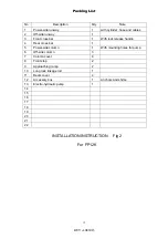
Page 18: ...Rear cross bar 1 5 Power side column 1 With mounting holes for pump 6 Off side column 3 7 Column cover 4 8 Front stop 2 9 Approaching ramp 2 10 Long lock linkage rod 1 11 Beam cover 4 12 Accessory box 1 Anchors and shims 13 Electro hydraulic pump 1 14 15 16 17 18 19 20 21 22 INSTALLATION INSTRUCTION Fig 2 For FP12K 15 Packing List REV A 083013 ...

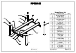
Page 19: ...D 928mm Length of Ramp E 910mm Length of Runway F 4860mm Width of Outside runway G 1980mm Width of runway H 482mm Size of Soleplate I 280 280mm Overall Length J 4960mm Lifting Height K 1760mm Overall Height L 2225mm Length between Columns M 4500mm Lifting Capacity 12000lbs Net Gross Weight 1000 1050 kg 16 REV A 083013 ...

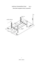
Page 20: ...INSTALLATION INSTRUCTION Fig 3 These data are suggestion not min requirement 17 REV A 083013 ...

Page 21: ...INSTALLATION INSTRUCTION Fig 20 18 REV A 083013 ...

Page 22: ...INSTALLATION INSTRUCTION Fig 21 19 REV A 083013 ...

Page 23: ... beam parts 2 1 6 Runaway 1 1 7 Runaway 2 1 7 1 Hexangular bolt C 9 7 2 Hexangular nut C 9 7 3 Flat washer C 9 7 4 Hexangular bolt C 3 8 Column cover 4 9 Front board 2 10 Small wheel 4 11 Front wheel block 2 58 Hydraulic rubber hose 1 59 Hydraulic hose fitting 2 60 Anchor bolt 16 61 Hexangular bolt C 4 62 Flat washer 4 63 Spring washer 4 64 Power unit 1 Easily Worn Parts Page 1 of 4 REV A 083013 ...

Page 24: ... 1 22 1 Inner hexangular screw 10 22 2 Flat washer C 10 22 3 Spring washer 10 23 Cable block 3 1 24 Cable block 4 1 25 Hydraulic cylinder 1 26 Set of beam wheel spindle 1 27 Beam wheel 1 6 27 1 Beam wheel spindle 1 1 27 2 Bush 6 27 3 Revolving oil cup A 2 28 Hexangular nut 8 29 Flat washer C 4 30 Inner hexangular screw 4 30 1 Flat washer C 4 31 Hydraulic cylinder spindle 1 31 1 Spindle spring wash...

Page 25: ...nsmission pole clasp 1 6 9 Hexangular nut 2 6 11 Hexangular bolt C 2 6 12 Flat washer C 4 6 13 Orientation bolt 4 6 14 Profiled bar connection 1 6 17 U Bolt 1 6 18 Hexangular nut 2 6 19 Spring washer 2 6 21 Flat washer C 2 10 1 Spring washer A 4 10 2 Hexangular nut 4 10 3 Flat washer 4 11 1 Hexangular bolt C 4 Easily Worn Parts Page 3 of 4 REV A 083013 ...

Page 26: ... Beam 1 jointing 1 38 Spindle 2 4 50 Spindle bush 2 4 38 1 Spring washer A 8 51 Wheel spindle 4 39 Spring 8 52 Spindle bush 1 4 40 Hexangular nut 16 53 Safty handle 1 40 1 Flat washer 8 54 Safty handle 1 41 Rubber block 8 55 Safty block 2 2 41 1 Cross bolt 8 56 Handle safty 2 2 41 2 Cross bolt 8 57 Safty handle pole Connet 1 2 41 3 Orientation board 4 57 1 Inner hexangular screw 4 41 4 Z Cross scr...

Page 27: ......
Page 28: ...owering valve See drawing below Step 2 Using an Allen wrench and shop towel with shop towel in place to catch fluid loosen the check valve plug 2 turns to allow it to leak Step 3 Push the START button for one second then release for three seconds Repeat these steps until unit starts pumping fluid Step 4 Tighten the check valve plug YOUR POWER UNIT SHOULD BE PRIMED ...

Reviews: