14
05
Installation
Manual 1843 Rev B p/n 001843 0000
DISCHARGE
OIL
MIST
ELIMINATOR
OIL
RETURN
LINE
GAS
BALLAST
ASSEMBLY
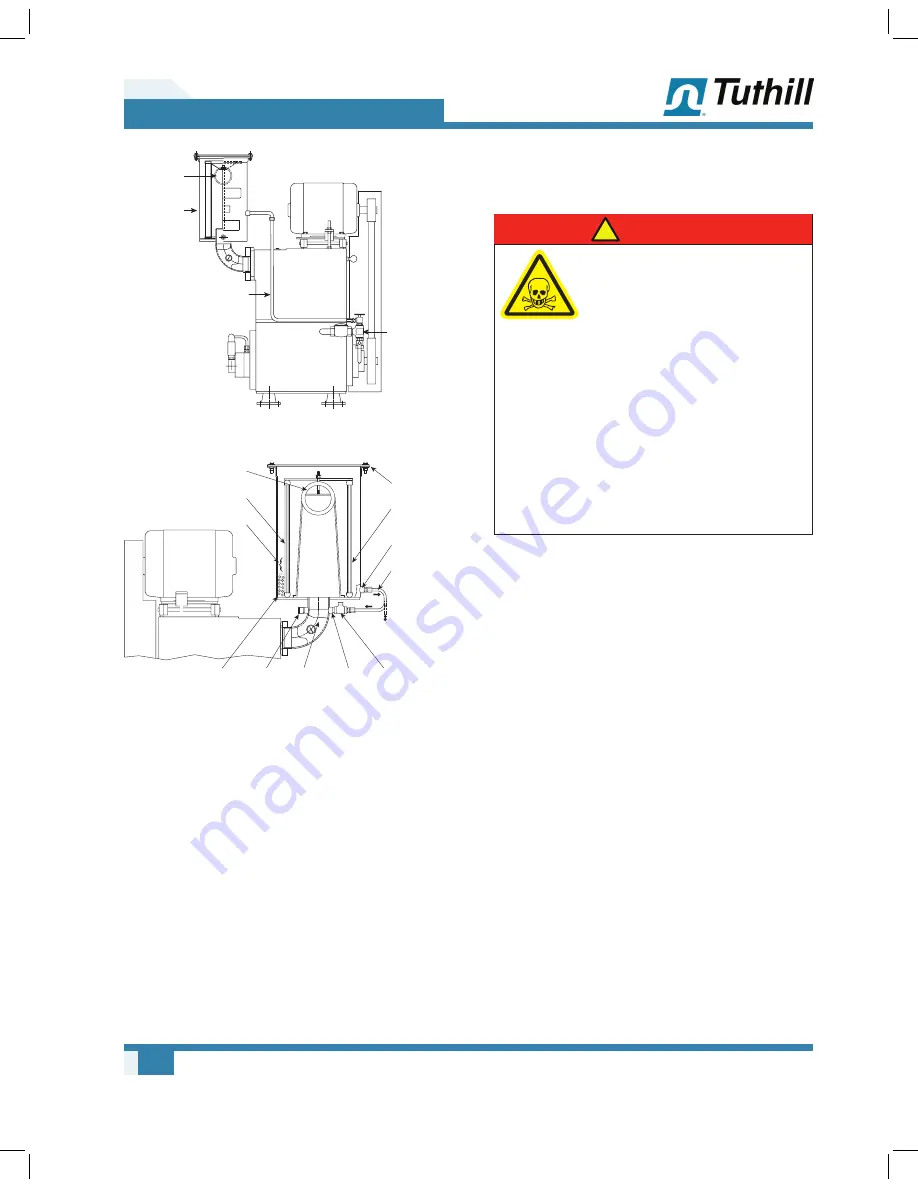
Figure 5-2 – Oil Return to the Gas Ballast Valve
OME DISCHARGE
CONNECTION
FIBER OUTER
SHELL (ELEMENT)
SATURATED
ZONE
OIL COLLECTS
AT BOTTOM
PRESSURE
GAUGE OR
PRESSURE
RELIEF VALVE
FIBER INNER
SHELL
(ELEMENT)
ALTERNATIVE TO THE
PUMP OIL RESERVOIR
OR GAS BALLAST
VALVE
OIL DRAIN
CONNECTION
OIL DRAIN
CHECK
VALVE
TOP COVER
GASKET
OIL MIST
FROM THE
PUMP (1)
OIL RETURN
CONNECTION
Figure 5-3 – Oil Mist Eliminator
It may be necessary to pipe the pump exhaust
fumes away from the pump area, such as
outdoors. If this is done, the piping must be
arranged to prevent line condensation from
returning to the pump. A flexible connector should
be fitted in the discharge line to provide freedom
for the vibramounts.
Hazards Associated With Hazardous
Process Fluids
DANGER
!
It shall be the responsibility
of the installer to ensure that
piping is adequate, sealing
between pipe joints is adequate
for the process fluids and
proper process and pressure
protection devices are in place.
It is also the responsibility
of the installer to assure
that process gasses are not
vented in a manner that would
be hazardous. Refer to the
manufacturer of the process
media to assure that proper
safety precautions are in place.
Cooling Water
The cylinder cooling water jacket is shipped dry.
Fill the water jacket before starting the pump.
If an optional water flow modulating valve (water
miser) is fitted, the cylinder may take 20 minutes or
more to fill. The delay can be avoided by manually
lifting the spring to open the valve. For installation
of the valve,
see Figure 5-4
.


