background image

Speed Gate Turnstile User Manual 


  Alarm 


Name 

Function 


Entrance guard system 


IC/ID card access control, fingerprint device,   

face recognition, QR code device,   

gate opening signal on the control board of   

gate machine, remote control,   

button to open the door (optional) 


Control board 

The control center of the system,   

which receives signals from the card reader 

  and infrared sensor, and makes logical judgment   

and processing of these signals,   

and then sends out execution commands to the 

  direction indicator, motor, counter and alarm. 

Infrared sensor 

Detect the position of pedestrians and safety protection 

Direction indicator 

Display the current traffic sign status of the gate   

and guide pedestrians through the gate 

Alarm (speaker) 

When the system detects a pedestrian illegally entering   

the passageway, it gives an alarm. 


Motor 

Drive the mechanism 

power supply Switch 

Control panel power supply 

www.TURNSTILES.us | [email protected] | 303-670-1099

Summary of Contents for DS7200

Page 1: ...he installation instructions before operating the equipment and save the instructions for future reference or for future users Speed Gate Turnstile User Manual www TURNSTILES us patrick mcallister TUR...

Page 2: ...ectronic control system of channel gate 4 2 Operating principle of the system 5 Equipment installation 5 1 Equipment installation instructions 6 Device function debugging 6 1 Key description 6 2 Funct...

Page 3: ...re requirements of the function in the case of emergency to ensure that the passage unimpeded convenient personnel timely evacuation 2 Functional Features 1 With zero self check function convenient fo...

Page 4: ...40 people min 4 Product Structure and Working Principle 4 1 Electronic control system of channel gate The electronic control system consists of card reader main control board infrared sensor directio...

Page 5: ...nd alarm Infrared sensor detect the pedestrian position and play the role of safety protection Direction indicator light displays the current status of the channel and guides pedestrians to pass throu...

Page 6: ...akes logical judgment and processing of these signals and then sends out execution commands to the direction indicator motor counter and alarm 3 Infrared sensor Detect the position of pedestrians and...

Page 7: ...ice the main control board controls the motor operation and the gate opens to allow pedestrians to pass D after the pedestrian passes through the channel according to the direction indicator sign the...

Page 8: ...s according to the packing list 2 After finishing the foundation surface of the installation equipment arrange the equipment well 3 After the hole location is determined drill the hole and embed the a...

Page 9: ...rotection 7 After check if the equipment status is normal the following function debugging can be carried out 8 Check the mains wiring according to the wiring diagram check the power wiring and other...

Page 10: ...ard from left right 1 left infrared sensor right swipe the card 2 right infrared sensor left swipe the card 3 infrared sensor left and right L 3 Delay closing time Set closing time after pedestrian pa...

Page 11: ...ticket continuous swipe mode default 0 without memory function 0 without memory function 1 with memory function L 10 Infrared anti pinch Set when pedestrians and other circumstances touch off the anti...

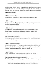
Page 12: ...ifferent brands of motors the default value is 1 do not change at will L 17 Reverse entry gate setting 0 means no close 1 means close and default value 0 do not change at will D 1 Zero setting of clos...

Page 13: ...s set according to the factory default Do not change D 7 Resistance rebound Mode When a pedestrian pass the channel and hit by the gate it will bounce back or keep closing default setting is 0 0 Hit t...

Page 14: ...tor strength setting the larger the value is the greater gate closing strength and the greater the vibration Value 1 100 default is 40 D 14 Power supply Adjust the power of the main board power value...

Page 15: ...the motor parameter value 1 200 default value 0 do not change at will D 23 Physical clamping reaction time This adjustment needs to contact the manufacturer s technical staff value 1 100 default valu...

Page 16: ...ue thick W Motor Hall GND black thin GND Hu yellow thin EU Hv green thin EV Hw blue thin EW 5V red thin 5V Motor wiring white blue and green Motor Name Color PCB screen print Motor phase W white thick...

Page 17: ...Speed Gate Turnstile User Manual www TURNSTILES us patrick mcallister TURNSTILES us 303 670 1099...

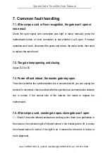
Page 18: ...the master gate stay open To recheck whether the synchronization line is connected well you can unplug the terminal to reconnect check and test whether synchronous communication network line is normal...

Page 19: ...Adjust D 10 and D 12 which arm is slower increase the value 7 6 Swing arm hits the gate frame 1 check the swing arm loose or not 2 manual reset the left open position right open position and closing...

Page 20: ...blems or product defects if the use or operation is not clear please timely contact the after sales service staff Warranty Card Warranty 3 years Order Date Product Name Product Model Customer Country...

Reviews:

Related manuals for DS7200