


6
Turn of the Century
TM
ASSEMBLY INSTRUCTIONS
7
5
6
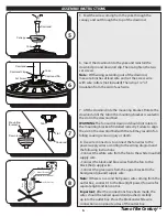
5. Feed the wires coming from the yoke through the
canopy and out through the top of the downrod.
6. Insert the downrod into the yoke and reinstall the
downrod pin and downrod clip. Then re-tighten the two
set screws.
Note:
With wiring extending out of the downrod,
measure 8 inches of lead wire and cut the excess wire
with wire cutters (not included). Then strip 1/2” of
insulation from the end of each wire.
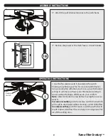
7. Lift the downrod into the mounting bracket. Rotate the
downrod until the tab in the mounting bracket is seated in
the slot in the downrod ball.
WARNING:
The fan and/or downrod should not rotate in
the mounting bracket if installed correctly. Failure to align
the slot in the downrod ball with the tab may result in fan
falling causing serious injury or death.
Downrod
Canopy
Downrod Pin
Yoke
Downrod
Downrod Clip
Set Screw
Yoke
Tab
Slot
Downrod
Downrod
Mounting
Bracket
Black (Hot)
Wire Connector
White (Neutral)
Bare/Green (Ground)
Black
Blue
White
Green
8. Use wire connectors to connect the fan wires to the
power supply wires according to the wiring diagram and
the following instructions:
• Connect the white wire from the fan to the white (neutral)
supply wire.
• Connect the black and blue wires from the fan to the
black (hot) supply wire.
• Connect the green wire from the upper bracket to the
bare/green (ground) supply wire.
Note:
If there is a second hot/power wire coming from the
outlet box, connect it to the blue (light power) fan wire for
separate light and fan control.
Important:
After the connections have been made, the
wires should be turned upward and pushed carefully
up into the outlet box. Place the black and white wire
connections on opposite sides of the outlet box.
8


