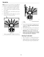
Operation
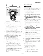
g027034
Figure 26
1.
Dial
2.
Diffuser
3.
Open the hopper gate to the maximum position
by pulling the rate dial and linkage outward.
Rotate the dial past the “9” position to the slot
opening and push in the linkage.
4.
Using a garden hose, spray the inside and outside
of the entire spreader with clean water.
Note:
Do Not use a power washer to clean the
machine. The high pressure water may force
residual corrosive materials into spreader-sprayer
components.
5.
When the hopper has been thoroughly rinsed and
drained, close the gate.
6.
Place the rate dial and linkage to a setting lower
than the maximum open position.
7.
Allow the spreader-sprayer to completely dry
before the next use.
8.
Lightly oil spreader components to help reduce
corrosion.
Spreader Calibration
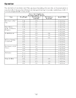
The spreader should be calibrated each time a new
material is used. The spread width ranges from 3-25
ft (0.9-7.6 m) and depends on the material particle
size, volume/density, and rate of travel.
Refer to the spreading charts along with
Determining the Distribution Pattern,
Determining the Effective Spreading Width,
and
Calculating the Application Rate
sections to
calibrate the machine.
Determining the Distribution Pattern
Operator supplied equipment:
15 shallow
collection pans and 15 graduated measuring cylinders
The most accurate method to measure the
distribution is to use shallow collection pans and
graduated measuring cylinders. In the example below,
15 shallow collection pans approximately 30 cm (12
inches) wide, 91 cm (36 inches) long, and 5 cm (2
inches) tall are used.
1.
Make sure to allow ample driving distance before
setting up the pans to ensure the machine is
traveling at the desired spreading speed before
reaching the pans.
2.
Place one pan in the center of the drive path.
Arrange the next two pans, one on each side,
far enough apart to allow ample room for the
spreader drive tires to pass over the center pan.
3.
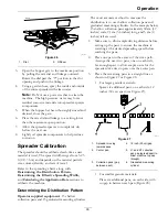
Place the remaining pans in a straight line as
shown in Figure 27 or Figure 28.
•
For larger granule materials:
Space six additional pans, on each side, 12
inches (30 cm) apart (see Figure 27).
g319659
Figure 27
1.
Spreader moving
towards pans
4.
12 inch (30 cm) gap
2.
Center pan
5.
L1 and R1 collection
pan gap (spread apart to
allow machine to pass
through)
3.
Collection pans (gap
between each)
6.
Graduated measuring
cylinder
•
For smaller granule materials:
Place six additional pans, on each side, with
no gap in between each pan (Figure 28).
33
Summary of Contents for Z-SPRAY JUNIOR Series
Page 1: ...Z SPRAY JUNIOR SERIES For Serial Nos 411 294 212 Higher Part No 4505 818 Rev A...
Page 60: ...Notes 60...
Page 61: ...Notes 61...
Page 62: ...Service Record Date Description of Work Done Service Done By 62...
Page 63: ...63...


