Rigging Manual
39
Inverted array
10.0.1 Required Components
Item
Quantity
TBV123-FB Flybar
1 (maximum)
TBV123 Cabinet
4 (maximum)
10.0.2 Location
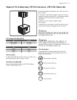
Move the first TBV123 cabinet so it is sitting upright on a safe flat surface,
directly below the suspension point.
10.0.3 Measured Weights
Please see Section 2.3 Weights on Page 9, and refer to EASE Focus Rigging
Parameters when designing your system.
TBV123-FB Flybar Working Load Limit (WLL)
Item
Working Load Limit (WLL)
TBV123-FB
100 kg
220.5 lbs
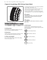
Chapter 10: Assembling an Inverted TBV123 Array
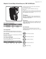
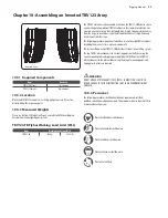
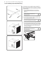
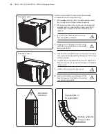
The TBV123 cabinets may be mounted inverted on the TBV123-FB flybar to create
a mirror-image to complement TBV123 cabinets in their normal orientation. For
example, a normal array on the right would have its high-frequency drivers away
from the stage; an inverted array on the left would also have its high-frequency
drivers away from the stage
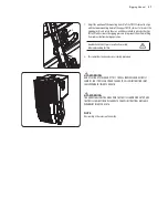
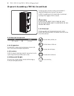
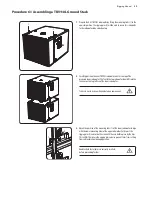
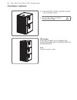
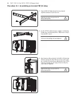
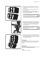
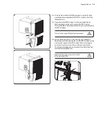
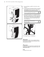
The following procedure shows how to build an array of inverted TBV123 cabinets
by adding them one at a time, up to a maximum of 4.
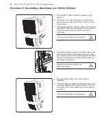
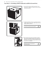
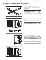
The system is flown using a TBV123-FB flybar that attaches to your lifting system.
The top TBV123 cabinet connects to 2 mounting points on the flybar, using the
2 extra mounting links and rigging pins supplied with the flybar. Each TBV123
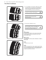
cabinet connects to the cabinet above using the integral mounting points and
rigging pins. No tools are required.
!
!
WARNING
DO NOT EXCEED A TOTAL QUANTITY OF 4 TBV123 CABINETS FOR 1 TBV123-FB
FLYBAR. FAILURE TO FOLLOW INSTRUCTIONS MAY CAUSE PERMANENT INJURY
OR DEATH.
10.0.4 Personnel
The following procedures shall be undertaken by experienced, certified,
qualified, and authorised personnel only. The procedures require the use of three
or more authorised persons.
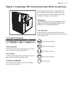
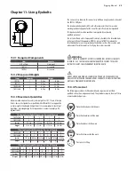
Protective Headwear shall be worn
Protective Footwear shall be worn
Protective Gloves shall be worn
Protective Eyewear shall be worn
Practice Safe Lifting
Summary of Contents for TBV118L-AN
Page 50: ......

