Rigging Manual
13
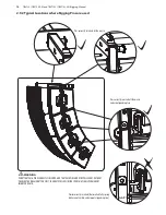
2.9.1 Rigging Pin Installation
Pin Installation
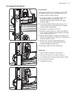
The following example shows how to use the rigging pins to join two TBV123
cabinets together. Exact details are given in later chapters of this manual.
1.
Support the weight of the cabinets to be joined.
2.
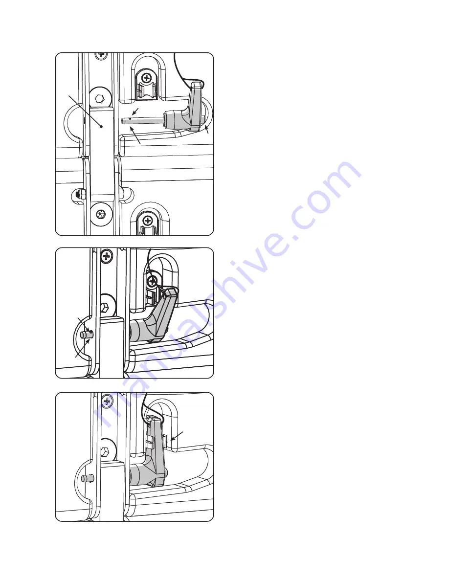
Align the top mounting link (1) of the lower TBV123 cabinet with the
corresponding mounting holes in the upper TBV123 cabinet.
Align the link with the mounting holes so the pin can pass through
and join them together.
3.
Press the button (2) at the end of the pin, and insert the pin in as far as
it will go. The spring balls (3) will retract while the button is being held,
allowing the pin to pass through the holes.
4.
Release the button (2) when the pin is fully inserted.
5.
Check the pin is correctly inserted as far as it will go, and that both spring
balls (3) are visible. Check that the components being connected have been
correctly captured together by the pin.
6.
With the weight of the components still supported, and without pressing
the button (2), try to pull on the pin sharply, to check it is secured in position
by the spring ball locking mechanism.
7.
Rotate the arm of the pin until it is captured by the spring clip (4).
This makes the pin extra secure, and will also prevent the pins from
vibrating and rattling when the speaker is in use.
8.
Repeat the pin installation for the other side of the cabinets.
Pin Removal
1.
Support the weight of the components to be disconnected.
2.
Rotate the arm of the pin until it is released by the spring clip (4).
3.
Press the button (2) and pull out the pin joining the components together.
4.
Do this for both sides of the cabinet.
5.
Carefully separate the cabinets.
1
2
3
3
4
3
3
Summary of Contents for TBV118L-AN
Page 50: ......


