background image

26

27

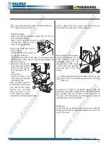
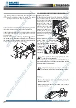
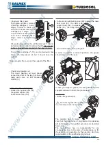
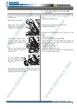
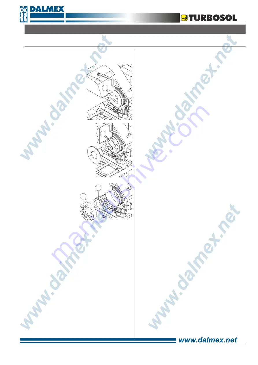
Change of the teethed wheel and the rubber ring of the 

centrifugal joint

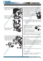
• Remove the accumulator. 

• Remove the cover of the cen-

trifugal  joint  removing  the  3 

hexagon head screws (76). 

• Remove  the  teethed    wheel 

and  the  rubber  ring  remo-

ving  the  three  hexagon  head 

screws (77). 

• Remove  the  teethed  wheel 

(79),  the  rubber  ring  (78)  and 

replace them.

• Fix  the  teethed  wheel 

and  the  rubber  ring  with 

the  three  hexagon  head 

screws (77). 

• Mount back the rubber clutch protecion lid of the cen-

trifugal joint fixing the three hexagon head screws (76) 

and place back the accumulator.

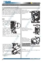
Operations  to  be  performed  every  year  or  every  100 

hours

• Change the compressor oil.

Operations to be performed every 200 hours

• Change the diesel filter.

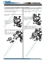
Operations  to  be  performed  every  6  months  or  500 

hours

Check:

• Check the air hoses.

• Check and eventually change the belts.

• Check  the  piston,  the  ball  valves,  the  seals,  the 

pressure  gauge,  the  by-pass,  and  generally  that  no 

anomalies are present.

• Change the compressor oil

• Change the gearbox oil.

• Change the gearbox mixer oil.

• Follow the instructions indicated on the diesel engine 

use and maintenance booklet.

7.3 - TO BE PERFORMED BY THE QUALIFIED  

        PERSONNEL

76

77

79

78

Summary of Contents for UNI 30 D

Page 1: ...ITALIANO PUMPING SYSTEMS FOR THE BUILDING INDUSTRY ENGLISH Serial number CT 200 359 ISTRUCTIONS FOR USE AND MAINTENANCE COMPREHENSIVE CATALOGUE SPARE PARTS ...

Page 2: ...ek 23 Machine not at work for long time 24 7 2 Change of wear and tear parts by qualified personnel 25 Change of the worn ball valves 25 Replace the gaskets of the inspection plugs 25 Changing the damaged valve s seats 26 Change of the worn piston 26 Change of the teethed wheel and the rubber ring of the centrifugal joint 27 7 3 To be performed by qualified personnel 27 Operations to be performed ...

Page 3: ...o persons and things resulting from unauthorized changes or modifications of this equipment MACHINE FOR CONVEYING AND SPRAYING TRADITIONAL STRUCTURAL AND SPECIAL MORTARS UNI 30 D The unit s serial number You are strongly advised to enter your equipment s serial number in the space above which must always be referred to in order to facilitate the work of the personnel in charge and it must likewise...

Page 4: ...4 ...
Page 5: ...ry which offers total reliability at low servicing costs Precautions to be taken when the machine is operating Maintenance or repair works must be carried out only when the machine is turned off Whatever safety devices have been removed in order to complete such work they must be mounted again after maintenance has been carried out Care and maintenance Care and maintenance are vitally important in...

Page 6: ...TION It is compulsory to read this maintenance booklet prior to operating the machine OBLIGATION It is compulsory to read this maintenance booklet with regard to regular and general maintenance Lifting point It is compulsory to grease the indicated point ...

Page 7: ... towards people In case of blockage of the gun no one should look directly into the hose of the deflector The sudden exit of the blocked part or of mortar under pressure may cause problems to the sight H Moving parts and hot parts are present inside the canopy as well as battery acids I Do not remove any protection L Before disconnectiong the material hose couplings or the spraygun make sure that ...

Page 8: ...machine A its serial number B and data on machine operating power are printed on the manufacturer s registration plate The meaning of the various symbols used is as follows A Type of machine UNI 30 D S MF UNI 30 D Machine with piston pump for pumping conveying and spraying traditional structural and special mortars S Standard version MF Version with fixed mixer B Machine s serial number NNNNNN AA ...

Page 9: ...es of nozzles Technical literature Accessories upon request On line pressure gauge for hoses Ø 50 Pumping nozzle for hoses Ø 40 Pumping nozzle for hoses Ø 50 Cement slurry injection device Hose extensions Hose extensions of 10 m mortar air Ø 50 x 66 e Ø 13 x 19 Hose extensions of 20 m mortar air Ø 50 x 66 e Ø 13 x 19 Main components The machine is made up primarily of a hopper 3 an agitator 4 a pi...

Page 10: ...100 every 500 hours Engine oil change diesel engine oil 15W40 check engine book Mixer gearbox oil change ELF Reductelf SP220 every 500 hours Hopper capacity 200 l Mixer capacity 180 l Delivery distance indicative 200 m Delivery height indicative 60 m Delivery hoses 1 Part special Ø 50 x 69 mm Extensions normal Ø 50 x 66 mm Final Ø 40 x 53 mm Maximum pumpable granulometry 8 mm Temperature in the wo...

Page 11: ...inimum length of the ropes 1 00 m for the ropes to be connected to the handles 1 30 m for the ropes to be connected to the tow bar 12 13 Use only hoisting equipment hooks and ropes that have been tested and approved for lifting at least 1000 kg Before lifting up the machine make sure that no one is standing too close to it The mortar mixed separately with whatever kind of mixer or prepared with th...

Page 12: ...e of a material coupling 16 an air coupling 17 an air cock 15 an air nozzle 18 a deflector 19 Generally with smaller size deflectors material is sprayed with a wider spray pattern and vice versa Through the by pass lever 20 it is possible to pump the material into the hoses horizontal position or to recycle it into the hopper vertical position Therefore it is possible to start the unit without loa...

Page 13: ...e proportions must be as follows 2 3 hydraulic lime 1 3 slaked lime 1 3 hydraulic lime 2 3 slaked lime 1 3 cement 2 3 slaked lime 2 3 cement 1 3 slaked lime Do not use plasticized aerated lime and whatever the case not in a percentage greater than one third of the binding agent Otherwise the machine s output will decline noticeably The mix must have a plastic consistency i e neither too dry nor to...

Page 14: ...ase the wear and tear on the hoses themselves The following hoses have to be used for the first 20 m special hose Ø 50 x 69 mm for the extension standard hoses Ø 50 x 66 mm terminal of 10 m Ø 40 x 53 mm Use always the complete hose length 20 10 10 even if exceeding the working needs Shorter hose lengths will cause discontinuous spraying Use only original hoses and couplings The connection between ...

Page 15: ...ck the levers of the cam lock coupling tightly 21 The longer hoses 20 m are always connected together to the machine and then the shorter hoses until the connection to the gun Connections Connect the mortar hoses to the pump group 22 and the air hose to the quick coupling of the air group 23 Then connect the spraygun to the final material hose 24 and to the air hose 25 locking the couplings tightl...

Page 16: ... clean diesel and close tightly Lubrication water Check that piston by lubrication tank is full with water Restore the level adding clean water in the proper opening 32 situated on top of the cylinder In winter add anti freeze in order to avoid the forming of ice or discharge the water whenever the ma chine is not working In any case the water has to be changed every 5 working days Gear lever Chec...

Page 17: ...ks make sure that all the safety devices are mounted back and that no tool is left inside the engine compartment or the material hopper 14 Tools or wipers left in the engine compartment may as well cause the brake down of the cooling fan Before starting the machine prepare the desired mix in a site or built in mixer and separately prepare 15 20 liters of slurry 50 water 50 cement or hydrated lime ...

Page 18: ... cock 37 the pump starts to push the slurry previou sly poured in the hopper With the by pass lever 20 always in vertical position recycle of material into the hopper check that the pump is engaged If this does not happen switch off the machine Make sure that the by pass lever 20 is in vertical position recycle of material into the hopper Caution the machine must always work with material or water...

Page 19: ...cal At the next start up the before mentioned lever has to be placed in pumping position horizontal In case of long stops open the discharge cock 38 and place the by pass lever in vertical position so that the mortar can be recycled into the hopper Make sure that the mortar in the hopper is always at such a level to cover the agitator If the level is not sufficient the pumping piston rubber will s...

Page 20: ... stage close the de livery air cock move the by pass lever to a vertical position 20 and make sure that the pressure gauge 45 shows 0 bar Switch off the engine by pulling the indicated head 40 then turn the key 39 to position 0 Before opening a coupling of the mortar hose or disconnecting the spraygun make sure that the pressure gauge indicates a pressure of 0 zero bar and that no pressure is rema...

Page 21: ...be damaged When the plastering machine has been completely washed you will then start with the cleaning of the mortar hose Insert the washing sponge in the hose Re connect the hose to the ma chine then re install the rubber ball valves the various plugs and the vibrating sieve so that the machine is ready to work again Make sure that the inspection plugs and the coupling between mortar hose and ma...

Page 22: ...mportant to follow the above described operations Pour in only oil SHELL RIMULA EXTRA D 15W40 Check the level of water in the cylinder make sure to empty it or to add the right proportion of antifreeze in winter in order to avoid the formation of ice during the stops In order to empty the cylin der remove the drain plug 52 In any case the water will have to be changed every 5 working days Engine o...

Page 23: ...perator which are responsability of the qualified personnel only Engine air filter check The engine air filter is made of 2 filtering cartridges 1 and 2 stage In order to check un screw the nut and remove the cartridge 54 1 stage In case traces of dust could be seen on the cartridge 55 2 stage remove it unscrewing the nut Hit gently various times the air filter element 1 54 on an hard surface in o...

Page 24: ...he various length of hose and then roll each piece up in order to avoid dangerous bents Protect the painted parts of the machine form rust spraying a layer of diesel or oil Avoid to spray directily on the rubber elements Lift the machine avoiding having the wheel touching the ground Check that the last wash up of the machine has been done following the instructions given that all the couplings hav...

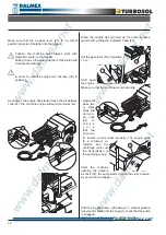
Page 25: ... are placed inside Replace the ball valves and mount everything back fixing tightly the tie rods Replace the gaskets of the inspection plugs In order to change the damaged valve s seat please follow this procedure Open the tie rods 48 working on the ring nuts with the standard key supplied 35 Remove the inspection plugs 41 49 from the valve s group and remove the gaskets 66 Change the gaskets and ...

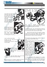
Page 26: ...ston has been changed re mount all the parts following the procedure above described 67 74 75 70 Changing of the damaged valve s seats In order to change the worn valve s seats proceed following the instructions given below Delivery valve s seat Remove the screw 67 that fixes the delivery valve s group on to the hopper and the 4 screws 68 that are blocking it on to the suction valve group Remove t...

Page 27: ...t fixing the three hexagon head screws 76 and place back the accumulator Operations to be performed every year or every 100 hours Change the compressor oil Operations to be performed every 200 hours Change the diesel filter Operations to be performed every 6 months or 500 hours Check Check the air hoses Check and eventually change the belts Check the piston the ball valves the seals the pressure g...

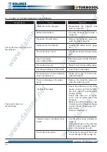
Page 28: ...he material is flowing freely from the hoses Blockage of the mortar hose An improper mix design see 6 2 or a long break could determine the blockage of the mortar delivery hose MATERIAL IS NOT FLOWING OUT OF THE SPRAYGUN AND THE MORTAR HOSE PRESSURE GAUGE SHOWS A HIGHER PRESSURE THAN THE NORMAL MAXIMUM WORKING PRESSURE OF 12 BAR In this case Close the air cock on the spraygun the machine stops Rel...

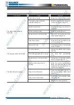
Page 29: ... supplied with the machine Remove the inspection plugs 41 49 from the valve s group and then remove the rubber ball valves 42 placed inside and wash properly the suction 43 and delivery 50 valves Remove the drain plug 51 of the suction collector Modify the mix design following procedure on page 13 Empty the hopper eventually using a strong flow of water Re mount all the parts back and make the new...

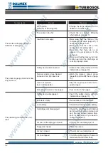
Page 30: ...tally open and the air discharge cock is properly closed page 18 Dirty nozzle Remove it and clean it Use the mortar hoses indicated on page 14 Use original hoses for the machine and the hoses suggested depen ding on the distance to reach Check the mix design of the mortar and eventually modify it page 13 Obstruction in the spraygun Mortar hose blocked Blockage in the ball valves Safety device not ...

Page 31: ... delivery valve page 21 and modify the mix page 13 Find the blockage and remove it page 28 Clean the mortar by pass Check the mix design and even tually modify it page 13 Clean the suction and delivery val ve s group page 29 Find the place where it is bent and make it straight Change the deflector with a larger size one Use sand finer granulometry curve Increase the q ty of binder Refer to the mix...

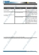
Page 32: ...ge 20 Re fuel diesel in the fuel tank Check the efficiency of the battery Check the centrifuge joint internal part should turn while external part and the belt should remain bloc ked In case worn off you need to change it page 27 Check it and eventually open it Clean the nozzle Check it and eventually open it Check the whole length of hose and make sure that air flows freely Worn piston Deflector ...

Page 33: ... tially blocked Check that the working pressure indicated on the mortar pressure gauge is not exceeding the ma ximum data shown on page 19 if this happens please modify the mix accordingly to what is indicated on page 13 and the hoses accordingly to page 14 The plastering machine starts alone while not engaged The plastering machine stops alone while engaged CAUSES REMEDIES 8 4 WORKS TO BE PERFORM...

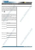
Page 34: ... is not used in accordance with the instructions in this manual In addition this manual must always accompany the machine The operator at the machine must be thoroughly taught and trained with regard to the operation and use of the machine itself and must sign this use and maintenance manual on the line reading read and approved If this procedure is not complied with the operator is prohibited fro...

Reviews: