background image


BASIC TUNING PARAMETERS 

It is important that the basic tuning parameters are discussed with a trained professional, please consult your ECU 
manufacture. There are a few basic parameters that are worth noting.  
 

Motor polarity is important,

 Due to the nature of PID controllers (Proportional-integral-derivative controller) the Anti lag 

valve 

will be targeting a set position, this will move further away if the motor polarity is wrong as it’s trying to reach it’s 

setpoint.


Current limitations

, it is important that the Current that is driven through the motor is limited to no more than 20amps for 

more than 1 second and 5 amps for more than 5 seconds. It is important that the current values such as the dead band are 
correctly set in the ECU to allow for the motor to only be active if needed.  
 

Sensor Diagnostic limits

 should be monitored for values that are lower than 0.1V and higher and 2.15V with respect to 

the Temperature sensor and 0.1V-4.9V with the position sensor. It is also recommended that safety tuning strategies are in 
place to lower temperatures if the Anti lag valve internally reaches a temperature of 150degC (302degF). 
 

Valve Position limits 

should be set to target 0% for valve closed and 90% for completely open, Since the design of the 

end stops is biased to operate better with the valve in the closed position it is recommended to avoid opening the valve to 
full lift. 


------------------------------------------------------------------------------------------------------------------------ 

WHAT’S NEW 


Our Electronic Anti-Lag Valves are a direct fit upgrade to all 5th-generation Turbosmart Anti lag valves and feature our unique collar-
locking system, variable motor cap and base, strap-type V-band clamps, liquid-

cooling, 1/8″ NPT ports.  


Control 

With the  introduction  of  the  electronic motor to  drive the  Anti  lag  valve,  a  new  level  of  control  is  now  available to  antilag  control 
strategies, there is a wide range of tuning strategies that can be implemented to better control  how antilag is operated. This allows 
the engine to maintain much better control of how the Anti lag valve is operated. 

 
Adjustability 

The 5th generation Anti lag valve range has been designed with maximum user-adjustability, without comprising performance. We 
designed this unit with almost infinite possibilities of directions in which the motor assembly can be mounted with the engine bay. So, 
if you need the Anti lag valve mounted in the opposite orientation to stop fouling with parts within the engine bay, there is an orientation 
that is suitable for the Anti lag valve to operate in. This mixed without the need of having to remove and reassemble due to changes 
in base spring pressure the Anti lag valve has next level control adjustability of the position of the valve.  
 

Upgrades and Servicing. 

Due to the modular construction, the new range is also upgradeable and completely serviceable, as all components can be removed 
or upgraded. Components have been tested for over one million cycles so reliability will be rock-solid. 

Flow and Thermal Performance 

Our new range of Anti lag valves out-flow all competitors thanks to our world-leading engineering and simulation abilities. Thermal 
performance has been improved drastically compared to our nearest rival, and all Anti lag valves feature liquid cooling ports for further 
thermal performance if required. 


Summary of Contents for Gen V eALV40

Page 1: ... antilag valve so that the electronic actuator is less than 100mm from a heat source DO NOT wrap the body of the antilag valve with exhaust wrap Fitting your Gen V antilag valve may require fabrication or modification to your exhaust manifold Turbosmart recommends that your antilag valve is fitted by an appropriately qualified technician Fitting the ALV to your turbocharger system introduces fresh...

Page 2: ...ERATURE 3 BASIC TUNING PARAMETERS 4 WHAT S NEW 4 GEN V ANTI LAG VALVE OVERVIEW 5 GEN V ALV Accessories 6 FITTING YOUR GEN V ALV 6 Connecting Your Anti lag valve 7 Calibration 8 Tuning 8 Sensor Linearisation 9 Tuning Strategies 9 ADVANCED FEATURES ON THE GEN V ANTI LAG VALVE 10 Re Orientation of the Actuator 10 Water Cooling 10 TROUBLESHOOTING 11 ...

Page 3: ...mportant to have the valve manually set to about the middle of its stroke as well as the valve seat installed This will allow for an easier installation Please see below for a more detailed and helpful way of installing the Turbosmart Gen V Anti lag valve MAINTENANCE Turbosmart s Gen V Anti lag valve will require periodic reapplication of spray grease such as Inox MX8 spray grease this is importan...

Page 4: ...re our unique collar locking system variable motor cap and base strap type V band clamps liquid cooling 1 8 NPT ports Control With the introduction of the electronic motor to drive the Anti lag valve a new level of control is now available to antilag control strategies there is a wide range of tuning strategies that can be implemented to better control how antilag is operated This allows the engin...

Page 5: ...valve Overview Inlet Adaptor Inlet V Band Outlet V Band Water Cooling port 1 8 NPT Wiring Loom Outlet Weld Flange Sold Separately Locking tabs Slave Collar Water cooling symbol Figure 3 Gen V eWastegate Water Cooling Figure 4 Gen V eWastegate Locking Collar ...

Page 6: ...nt of restriction will achieve a higher amount of usable energy in the manifold CAUTION Do not place the actuator cap near a significant heat source as this could shorten the life of the diaphragm CAUTION Use of the Antilag valve produces excessive heat in the exhaust manifold and turbo and may result in shorter than expected life Plumbing the antilag valve into the exhaust port maximises the ther...

Page 7: ...commends calibrating the position sensor before connecting the motor wires to your motor drive The two large wires are directly connected to the motor of the anti lag valve and need to be connected to high power drives in a Full bridge configuration like that of an electronic throttle drive circuit see your ECU supplier documents for suitable connections Turbosmart recommends the anti lag valve sh...

Page 8: ...sition rotate the adjustment 2 full turns in a clockwise direction Read the sensor value and set this as 100 valve travel Monitor sensor signal voltage to ensure no wrap around occurs throughout the stroke of the valve that could affect operation CAUTION It is critical not to set the 100 position at the end of the travel as this may lead to seizing of the anti lag valve and overloading the system ...

Page 9: ...home positions and for this reason the calibration sequence with low force is essential y 0 5596x3 1 8306x2 2 2847x 0 0189 R2 0 9989 Tuning Strategies CAUTION Tuning your antilag valve should be done by a professional Antilag valve is for race applications only The use of antilag creates excessive heat in the exhaust manifold and can shorten the life of turbo exhaust manifold and related systems A...

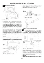
Page 10: ... seat installed to prevent damage to the valve Tighten the collar using a torque wrench on the 3 8 square drive provided in the collar tool perpendicular to the length of the tool to 30N m 22ft lbs Fold down a tab onto the slave collar to prevent the collar from coming loose during use Water Cooling Turbosmart s Gen V anti lag valve is equipped with water cooling ports to keep the anti lag valve c...

Page 11: ...that is driving the valve may not be set up correctly Wraparound of signal on position sensor Turbosmart Pre time every sensor contact Turbosmart if this occurs Antilag valve seized Remove cap and manually move valve feeling for resistance Antilag valve moves but sensor not reading Check connections Failing the above submit a technical request to tech turbosmart com au with information of your eng...

Reviews: