


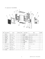
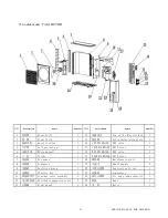

39 SERVICE MANUAL FOR AMERICA
一
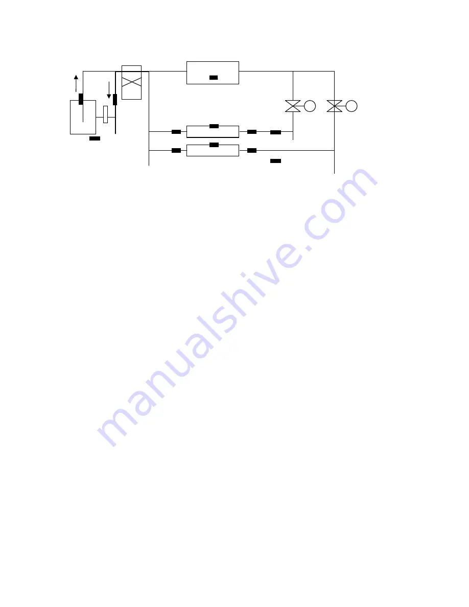
. System Frame Drawing
R
everse Valve
(
Current in cooling condition
)
Condenser of Outdoor Unit
Temperature of the Middle of Outdoor Coils
Temperature of Exhaust
Expansion Valve 1 Expansion Valve 2
Temperature of suction
M M
Compressor
L
iquid Tank
T11 T12 T13
Evaporator 1 of Indoor Unit
Ambient Temperature of Indoor 1
Ambient Temperature of Outdoor T21 T22 T23
Evaporator 2 of Indoor Unit
Ambient Temperature of Indoor 2
Diagram 1
二.
Major Performance Index
a)
Voltage of Power Supply
: AC220V ±15%;
b)
Power of Controller
: ≤15W;
c)
Output of Three-phase Frequency Conversion
:
Wire Voltage: 70V
∽
180V; Power:
≤
5KW; Frequency: 10Hz
∽
120Hz;
d)
Precision of Temperature Control
:
±1
℃
;
e)
Applicable Environment
:
Temperature:-20
∽
55
℃,
Relative Humidity:
≤
90%RH (No dew);
f)
Conservation Environment
:
Temperature:-25
∽
70
℃,
Relative Humidity:
≤
95%RH (No dew);
g)
Executive Standard: GB/T7725-2004 & GB4706.32-2000.
三.
Input & Output of Outdoor Controller
1.
Outputs of one three-phase Frequency Conversion, two relays, one indicator led and one
communication signal
:
1)
Controlling the three-phase output of compressor
2)
Controlling the output of outdoor motor
3)
Controlling the output of 4-way valve
4)
Controlling the output of communication signals of indoor unit
5)
Controlling the output of expansion valve
2.
Inputs of five analogue inputs (the temperature measuring points distributing as Diagram 1, all the
analogues go through digital filter for disposal), and two switch signals and two communication
signals:
a)
Signal input of outdoor ambient temperature
b)
Signal input of median temperature of outdoor coil
c)
Signal input of discharge temperature of compressor
d)
Signal input of suction temperature of compressor
e)
Signal input of power supply voltage
f)
over-heat protection signal of compressor
g)
communication signal of indoor unit 1
h)
communication signal of indoor unit 2
i)
protection signal of outdoor IPM module
四
. Operation in Cooling Mode