background image

16 


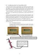
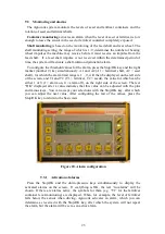
Figure 12. Down-pressure value P=11 


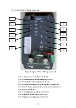
Figure 13. Maximum down-pressure P=15 

Adjusting down-pressure while seeding 

The down-pressure value mentioned above is the lowest limit value, which 

determines when the system will stop the hydraulic lowering of the machine.   The 
down-pressure of the machine can be decreased during driving and increased again 
using hydraulics at areas where the pressure is lower than the maximum down-
pressure set. If you want to increase the down-pressure during driving  you must first 
increase the maximum down-pressure  electronically and then lower the the machine 
hydraulically. In some situations, the maximum value cannot be reached if the soil is 
extremely hard and if the container has a light load. 

When adjusting the down-pressure manually, the relative amount of down-pressure 

is shown on the front panel of the seed fertilizer. 

The down-pressure is suitable for seeding when the bearing wheels of the seed 

fertilizer containers roll along the ground but do not bear the load caused by the 
down-pressure to a significant extent.  When this is the case, the seeding depth is as 
close as possible to the value chosen from the bearing wheel. 

Down-

pressure 

value (1-15) 

Summary of Contents for AgroCont

Page 1: ...98801803 E 8 11 2017 AgroCont and AgroCont plus Manual and sparepart book Starting from machine number AD 51612 Please read this manual before you start using the system Translation...

Page 2: ...2...

Page 3: ...li Address Sudenkorventie 1 FI 14200 Turenki Hereby declares that Seed drill control system Agrocont and Agrocont plus Serial number _______ are in compliance with the applicable decrees of the Machin...

Page 4: ...Amount of fertilizer plus model only 12 8 Keys 13 8 1 Hectare counters HA and dHA 14 8 2 Plus 14 8 3 Minus 14 8 4 Stop OK 14 8 5 Tramlining device 14 8 5 1 Changing the current rhythm position 14 8 5...

Page 5: ...in use 27 12 1 12 Indicator for markers pole lifting feature 27 12 1 13 Type plate 27 12 2 Agrocont Nova TItan processor unit 28 12 2 1 Advance sensor s indicator cf 11 1 1 28 12 2 2 Fertilizing shaf...

Page 6: ...herwise necessary shields have been opened or removed from some images in order to give a better view of the object being shown The machine must not however be used without the shields in place For yo...

Page 7: ...the system depends on the basic machine You must never go under a machine marker etc when it is hydraulically raised If it is necessary to go under such a machine or object the machine or object must...

Page 8: ...dimensions and coupling The power supply to the socket must be powerful enough to allow a continuous input of 25 A while the voltage must when the engine of the tractor is running and even when the t...

Page 9: ...9 Figure 2 Data cable connected Figure 3 Data cable socket Figure 4 Data cable plug...

Page 10: ...ractor and on the user s preference Usually the best position is either to the right or right front of the driver When placing the monitor in the cab you should consider various factors such as sunlig...

Page 11: ...he connector press it lightly and turn the locking part When the system power is switched on Agrocont s preset values appear on the display immediately after the system has loaded When the system is s...

Page 12: ...12 7 Display Figure 8 Monitor type plate Figure 9 Basic view of the system 7 1 Areas 7 2 Wheel tracks 7 3 Down pressure 7 4 Level mode 7 5 Amount of fertilizer plus model only 7 1 7 2 7 3 7 4 7 5...

Page 13: ...13 8 Keys Figure 10 Agrocont plus model keys and display Figure 11 Agrocont model keys and display 1 2 3 4 5 6 7 8 9 10 1 2 3 4 5 6 7 8 9 10...

Page 14: ...hese functions are explained later in this manual The position of the tramlining device is shown in the bottom left corner where the first of the numbers e g 1 5 presenting the order in which wheel tr...

Page 15: ...the system into stop mode meaning that the marker changer will not react even though the seeder is being raised and lowered Remember to exit stop mode immediately after an additional lift or when seed...

Page 16: ...ou must first increase the maximum down pressure electronically and then lower the the machine hydraulically In some situations the maximum value cannot be reached if the soil is extremely hard and if...

Page 17: ...ly The value for the low lift setting will appear on the bottom row of the screen e g HALF 5 The value with a range of 1 9 can be changed with the plus and minus keys To save the desired value press t...

Page 18: ...bove the key will be lit if a marker is activated A light above both keys indicates that the automatic marker change function is activated When you raise or lower the seed fertilizer the markers are r...

Page 19: ...t or the marker changer to change Remember to disable the Stop OK mode after passing the obstruction Raising a marker without interrupting seeding See section 8 8 Extra lift function Starting seeding...

Page 20: ...r draws a line to the centre of the previously sown furrow stage So the mark works as a centre mark during spraying The Ritsi marking function is switched on by pressing the STOP OK button and the but...

Page 21: ...d with the plus and minus keys and accepted with the Stop OK key The desired value can be accepted with the Stop OK key Figure 18 Setting up working width 9 2 Advance distances The table below illustr...

Page 22: ...tion roller P1350 PTD Multimaster 79 40 175 70 R 13 183 92 185 65 R 15 194 97 685 190x15 196 980 7 00 12 206 103 10 0 75 15 3 250 125 11 5 80 15 3 262 131 400 60 15 5 275 137 11 2 20 300 150 15 0 70 1...

Page 23: ...larm limit range is 1 9 will then be displayed on the left side of the screen and T1 and T2 T1 fertilizer T2 seeds the value for which can be either 1 or 0 1 alarm on 0 alarm off on the right side of...

Page 24: ...corner of the screen When you push a quick selection key the green LED light and the figure on the screen showing the amount of fertilizer will start blinking Configuration of the desired selection w...

Page 25: ...feed rollers to the middle position Next conduct a test run in accordance with the instructions for the given seed fertilizer enter the measurement result into the amount to be sown kg ha field and ac...

Page 26: ...d low lift electro hydraulics for the coulters and in Nova models the lift down pressure control are attached The symbols and the LED lights in the unit on the left 1 to 6 notify about information sen...

Page 27: ...seeds 12 1 6 Elimination sensor indicator This LED light is illuminated when the seed fertilizer is raised 12 1 7 Tramlining device indicator This LED light is illuminated when voltage is applied to t...

Page 28: ...or cf 11 1 2 12 2 3 Seed shaft rotation indicator cf 11 1 3 12 2 4 Fertilizer container level control sensor s indicator cf 11 1 4 12 2 5 Seed container level control sensor s indicator cf 11 1 5 12 2...

Page 29: ...the machine are relatively empty the machine may not lower itself to the low limit but the weight of the machine will be used to determine the maximum down pressure 12 2 12 Indicator for Nova Titan s...

Page 30: ...y which does not require an additional power source Repair and software updating should only be performed by an authorised Tume service agent Do not open the casing of the monitor or working machine c...

Page 31: ...ING FROM MACHINE NUMBERS R in program version see section 8 11 Ritsi marking JC Titan Nova AD 51321 AD 51612 AD 51363 AD 51323 AD 51395 AD 51212 AD 51512 AD 51488 AD 51516 AD 51638 AD 51523 AD 51528 A...

Page 32: ...grocont 1 1 3 99263302 Prosessori AC AC plus NOVA Prosessor Agrocont plus Prosessor Agrocont plus 1 1 3 99263402 Prosessori AC AC plus Titan Prosessor AC and AC Prosessor AC and AC 1 1 4 98722608 J nn...

Page 33: ...13 02051065 Kulma anturi nostolle NOVA Angle sensor for machine lift Vinkelgivare till maskin lyft 1 1 14 98722616 S hk kaapeli Hydr venttiileille sis liittimen Cabel for hydraulic valves include pin...

Page 34: ...Pulse sensor seed shaft Lannoites ili n pinnanvalvonta anturi Tramline system Oikean merkkari venttiili Siemens ili n pinnanvalvonta anturi kapasitiivinen Fertilizer remote control system actuator Lef...

Page 35: ...44 2 43 3 42 4 41 5 40 6 39 7 L11 38 8 37 J21 9 L15 36 10 35 11 34 12 33 13 L12 32 7 8 9 10 14 31 L5 15 30 1 16 29 2 17 L13 3 L4 18 4 19 5 20 6 21 L14 28 L6 22 27 11 12 13 14 23 26 24 25 J20 AGROCONT...

Page 36: ...1 2 3 4 5 6 L7 UP 1 2 DOWN 1 L10 L16 44 2 43 3 42 4 41 5 40 6 39 7 L11 38 8 37 9 L15 36 10 35 11 34 12 33 13 L12 32 14 31 15 30 J4 16 29 17 L13 18 19 20 21 L14 28 22 27 23 26 24 25 GND AGROCONT COUPLI...

Page 37: ...3 WIRE L6 TRAMLINE FUSES WIRE 17 Angle sensor J4 1 11 12V J3 1 18 Angle sensor J4 2 12 12V J3 2 19 Angle sensor J4 3 yell green 13 0 V J3 3 20 actuator motor fertilizer adj J11 black 14 0 V J3 4 yell...

Page 38: ...16 monitor 0 V J2 4 yell green L13 WIRE L4 TRAMLINE FUSES WIRE 17 11 12V J3 1 18 pulse sensor for tramline counter J10 1 12 12V J3 2 19 pulse sensor for tramline counter J10 2 13 0 V J3 3 20 actuator...

Page 39: ...2 14 monitor data J2 2 0 V J3 3 J3 4 15 monitor 12V J2 3 16 monitor 0 V J2 4 yell green L7 TITAN SOVITIN WIRE L13 WIRE 1 pulse sensor up J10 1 17 titan adapter J4 1 2 pulse sensor up J10 2 18 titan ad...

Page 40: ...PL 77 FI 14201 Turenki Finland Tel 358 207 433 060 Fax 358 3 688 2305 www tumeagri fi...

Reviews: