13
ASSEMBLY
ASSEMBLY
ASSEMBLY
ASSEMBLY
GEAR
GEAR
GEAR
GEARBOX
BOX
BOX
BOX ASSEMBLY
ASSEMBLY
ASSEMBLY
ASSEMBLY
1. Press the bearings (20) onto the
worm (44) then install the worm and
bearings into the housing (39).
2.
For winches driven by a hydraulic
motor:
Press a new oil seal (19) into the
motor adapter (60). Attach the motor
adapter (60) to the housing (39) with
six capscrews (80), using gasket
(11). Install the motor (57) with two
capscrews (58) and washers (61).
For winches driven by a PTO
sprocket and chain:
Press a new oil seal (19) into the end
cap (45). Attach the end cap (45) to
the housing (39) with six capscrews
(18) using gasket (11).
3. Install the keys (36) into the output
shaft (37).
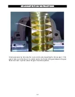
4. Bolt the gear (28) to the carrier (40)
using twelve capscrews (35), nuts
(12), and washers (13).
5. Install the assembled gear onto the
shaft (37). Press the roll pin (41) into
the carrier (40). Slide the bushings
(21) on to both ends of the output
shaft (37).
6. Install the output shaft ass’y into the
housing (39).
7. Attach the cover (26) to the housing
(39), using capscrews (24 and 25),
nuts (12), washers (13), using
gaskets (27).
8. Fill the gearbox and brake with the
proper oil. Refer to the maintenance
section of this manual for oil type and
amount.


