background image

28545

Operator’s Manual

Keep this manual with the machine at all times.

Bale Packer

Ac2/+4

PRINTED IN CANADA

Tubeline Manufacturing Limited

6455 Reid Woods Drive RR #4

Elmira, Ontario, Canada N3B 2Z3

Email:


[email protected]

Fax: 519.669.5808

Tel: 519.669.9488

Toll-free (North America): 1.888.856.6613

www.tubeline.ca

Rev. 2-0

Do not attempt to operate this machine without thoroughly 

reviewing this manual for safe and proper operation.

Summary of Contents for Accumul8

Page 1: ...beline Manufacturing Limited 6455 Reid Woods Drive RR 4 Elmira Ontario Canada N3B 2Z3 Email sales tubeline ca Fax 519 669 5808 Tel 519 669 9488 Toll free North America 1 888 856 6613 www tubeline ca R...

Page 2: ...isuse by his employees or others Manuals Operator s manuals are printed and shipped with machines as they leave the manufacturer Your machine may include parts or features not yet included in the init...

Page 3: ...y 2 4 Safety Signs 2 4 Safety Sign Locations 2 5 ISO Safety Decal Locations 2 5 ISO Safety Decals 2 6 Section 3 Adjustments 3 1 Initial Setup 3 1 Initial Setup Rear Wheels 3 1 Initial Setup Cables 3 1...

Page 4: ...ice 6 1 Grease Points 6 2 Troubleshooting 6 4 Section 7 Parts Breakdowns Lists 7 1 Bale Chute All Models 7 2 Wheels Axles All Models 7 4 Bale Gate All Models 7 6 Front Bale Guides All Models 7 8 Endga...

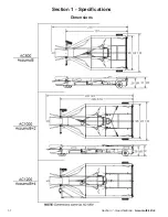
Page 5: ...1 1 Section 1 Specifications Accumul8 2 4 Section 1 Specifications Dimensions...

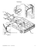
Page 6: ...Accumul8 2 4 Section 1 Specifications 1 2 Terminology Bale Chute Bale Gate Trip Endgate Trip Endgate Bale Guide Arm x2 Bale Gate...

Page 7: ...32nds 62mph Bale Sizes The Accumul8 AC800 and Accumul8 4 AC1200 can handle bales from 32 42 inches 81 106 cm long The Accumul8 2 AC1000 can handle bales 34 38 inches 86 96 cm long The maximum bale wi...

Page 8: ...ttention Become Alert Your Safety is involved Study the features in this manual and make them a working part of your safety program Keep in mind that this safety section is written only for the Nitro...

Page 9: ...ook WARNING Only use a tractor with a ROPS cab and seat belt Secure your seat belt before operating machine DANGER Never allow riders on manure spreader There is no safe place for any riders even for...

Page 10: ...g procedures when mounting a tire on a wheel or rim can produce an explosion which may result in serious injury or death Do not attempt to mount a tire unless you have the proper equipment and experie...

Page 11: ...mpleting maintenance or service function make sure all safety shields and devices are installed before placing unit in service Transport Safety 4 Do no exceed 32kph 20mph during transport Safety Signs...

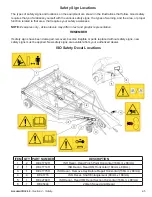
Page 12: ...entation REMEMBER If safety signs have been damaged removed become illegible or parts replaced without safety signs new safety signs must be applied New safety signs are available from your authorized...

Page 13: ...s Item 6 DE42784H Do not exceed 20mph 32km h when towing this equipment Item 1 DE41712H Stand clear of endgate to avoid pinching hazard Item 2 DE41714H Read and understand owners manual before operati...

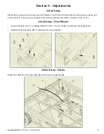
Page 14: ...s cables and you will need to setup your accumulator to be either towed behind a baler or behind a truck or ATV Initial Setup Rear Wheels Loosen and take out 13 carriage bolts 1 and 13 lock nut 2 and...

Page 15: ...olts and 1 2 13 lock nuts Fig 1 10 12 Bale Kit Installation The Tube line Accumulator has the ability to accumulate 10 or 12 bale packs depending on which kit you have installed 10 Bale Kit Installati...

Page 16: ...Adjustments 3 3 3 Insert side guide 6 in hole location 7 4 Retain side guide 6 with spring handle 3 and secure with 3 8 16 bolt 4 and 3 8 16 nut 5 5 Connect 7 spring 8 into eyebolt 9 and spring handl...

Page 17: ...bale kit will only work if you have an Accumul8 it will not work if you have an Accumul8 NOTE Setup assumes no kit has been installed 1 Insert bale guide 1 into location 2 on the Accumulator 2 Retain...

Page 18: ...ting the tension to high will cause the bales to jam adjusting the tension too loose then the gate will not swing over before the next bale The bale guide arms 2 allow the Tube line Accumulator to div...

Page 19: ...rip too soon and you will not get a tight pack too far back and it won t trip the back gate at all NOTE Use the threaded rod the fine tune adjust when the endgate opens not enough tension and the endg...

Page 20: ...g into one of the holes to set the tension of the arms NOTE With too much tension the incoming bale will not be able to push the arm back not enough and the arms will not travel back to its home posit...

Page 21: ...secure Baler Hookup Reverse the baler to the Tube line Accumulator or pull the Accumulator to the back hitch of the baler and insert hitch pin through the baler and the Accumulator NOTE Some balers do...

Page 22: ...ulled behind an ATV or truck Below you will find an outline of its functions The offset hitch consists of 3 main components 1 Hitch tube assembly 2 Hitch offset assembly 3 Hitch tube brace The offset...

Page 23: ...2 4 3 Attach bale chute 6 into Accumulator holes 7 and secure with 3 16 cotter pins 8 4 Attach hitch 9 to center dolly 1 with hitch pin 10 and secure with 3 16 cotter pin 11 5 Set bale slide 12 in it...

Page 24: ...Accumul8 2 4 Section 4 Transportation 4 4 Towing with Truck ATV 1 Remove shute 1 2 Remove hitch 2 6 Remove flares 13...

Page 25: ...ion Accumul8 2 4 3 Remove center dolly 3 from center position 4 4 Insert center dolly 3 into outer dolly position 5 and contain with washer 6 and lynch pin 7 5 Insert flare 9 into slot and secure with...

Page 26: ...Accumul8 2 4 Section 4 Transportation 4 6 6 Set bale slide 13 to it s raised position...

Page 27: ...h are activated by the passing bales entering into the Accumulator which cause it to function Gathering Bales Before collecting bales with the Accumulator a method of gathering must be chosen Fig 1 sh...

Page 28: ...same pattern with each layer See AC1000 Operation pg 5 6 1 Bale number 1 enters the Accumulator in the chute area 1 and proceeds past the front gate and trips the gate trip in area 2 causing the front...

Page 29: ...3 follows the same procedure as bale number 1 but continues to trip the front arm in area 3 2 Bale number 2 follows the same procedure as bale number 1 except on the opposite side Illustration below s...

Page 30: ...7 Bale number 7 follows the same procedure as bale 5 4 Bale number 4 follows the same the same procedure as bale number 3 but on the opposite side 5 Bale number 5 follows the same procedure as bale 3...

Page 31: ...s same procedure as bale 6 but trips bale trip lever in area 5 which releases bales out rear gate as Accumulator is pulled forwards See pg 5 9 for further illustrations and procedures taking note that...

Page 32: ...rm It stops parallel to the endgate 2 The second bale follows the same path as bale 1 but on the opposite side It will end up in line with bale 1 parallel to the endgate Illustrations below show how t...

Page 33: ...trigger the front bale guides to flip towards sides of frames allowing bales 7 to 10 to enter the middle columns 3 The third and fourth bales follow the same paths as bales 1 and 2 but do not get rota...

Page 34: ...le columns they will each trigger an endgate trip The endgate will not raise and release bale pack until both endgate trips are fully activated NOTE If endgate does not trip the cable will need to be...

Page 35: ...which tightens the cable running to the endgate As the endgate cable is tightened and pulled towards front the endgate pivot raises the endgate latches allowing the endgate to swing freely and open f...

Page 36: ...following checks and adjustments Be alert for loose hardware and tighten or replace as required Lubricate the Accumulator according the instructions in the Lubrication section of this manual Under ad...

Page 37: ...4 Grease Points Caster greaser 1 Apply 4 strokes at point 1 daily Caster spindle 2 Apply 4 strokes of grease at point 2 daily Gate pivot 3 Apply 4 strokes of grease at point 3 daily Hub 4 Apply 1 stro...

Page 38: ...vot 5 Apply 4 strokes of grease at point 5 daily Bale Trip 6 Apply 4 strokes of grease at point 6 daily Bale Guide 7 AC1000 Accumul8 2 Apply 4 strokes of grease to point 7 daily Bale Latch 8 AC1000 Ac...

Page 39: ...ss though side swing arms causing the machine to jam up Cause 1 Spring tension on swing arms too tight Cause 2 Stop bolt on swing arm not set correctly Suggested Remedy 1 Loosen spring tension or remo...

Page 40: ...Accumul8 2 4 Section 7 Parts Breakdowns Lists 7 1 Section 7 Parts Breakdowns Lists...

Page 41: ...7 2 Section 7 Parts Breakdowns Lists Accumul8 2 4 Bale Chute All Models...

Page 42: ...te Set Pin 8 2 FW 1 2 Flatwasher 1 2 Zinc Plated USS 9 2 FW 3 4 Flatwasher 3 4 Zinc Plated USS 10 2 HB 1 2 13X4 5 Z5 Hex Bolt 1 2 13x4 1 2 Grade 5 Zinc Plated Hex Cap Screw 11 1 HB 3 4 10X1 5 Z5 Hex B...

Page 43: ...7 4 Section 7 Parts Breakdowns Lists Accumul8 2 4 Wheels Axles All Models...

Page 44: ...t 1 2 13 x 1 1 2 Grade 5 Zinc 10 2 FW 1 2 Flatwasher 1 2 Zinc Plated USS 11 2 FW 3 4 Flatwasher 3 4 Zinc Plated USS 12 7 GR 3 16D 3 16 Drive Straight Grease Fitting 13 2 HB 1 2 13X1 5 Z5 Hex Bolt 1 2...

Page 45: ...7 6 Section 7 Parts Breakdowns Lists Accumul8 2 4 Bale Gate All Models...

Page 46: ...ute Set Pin 8 2 FW 1 2 Flatwasher 1 2 Zinc Plated USS 9 2 FW 3 4 Flatwasher 3 4 Zinc Plated USS 10 2 HB 1 2 13X4 5 Z5 Hex Bolt 1 2 13x4 1 2 Grade 5 Zinc Plated Hex Cap Screw 11 1 HB 3 4 10X1 5 Z5 Hex...

Page 47: ...7 8 Section 7 Parts Breakdowns Lists Accumul8 2 4 Front Bale Guides All Models...

Page 48: ...raight Grease Fitting 11 8 HB 1 2 13X1 5 Z5 Hex Bolt 1 2 13x1 1 2 Grade 5 Zinc Plated Hex Cap Screw 12 2 HB 1 2 13X2 Z5 Hex Bolt 1 2 13x2 Grade 5 Zinc Plated Hex Cap Screw 13 4 HB 3 8 16X1 25 Z5 Hex B...

Page 49: ...7 10 Section 7 Parts Breakdowns Lists Accumul8 2 4 Endgate All Models...

Page 50: ...t Endgate Latch 6 2 AC A 121 Latch Trip Rod 7 2 CP 18X1 Pin Cotter 1 8 X 1 0 8 6 FW 1 2 Flatwasher 1 2 Zinc Plated USS 9 2 HB 1 2 13X1 5 Z5 Hex Bolt 1 2 13x1 1 2 Grade 5 Zinc Plated Hex Cap Screw 10 2...

Page 51: ...ye Bolt 3 8 16 X 2 1 2 Shank Zinc Plated Turned 5 1 EB3 8 16X8 0 Eye Bolt 3 8 16 X 8 Galvanized Machine Threaded 6 2 FW 3 4 Flatwasher 3 4 Zinc Plated USS 7 2 FW 3 8 Flatwasher 3 8 Zinc Plated USS 8 4...

Page 52: ...t Hitch All Models ITEM QTY PART NUMBER DESCRIPTION 1 1 AC A 19 Hitch Tube 2 1 AC A 20 Hitch Offset 3 1 AC A 21 Hitch Tube Brace 4 3 LN1 2 13NCZ2 1 2 13 Grade 2 Zinc Finish NE Steel Nylon Insert Lock...

Page 53: ...7 14 Section 7 Parts Breakdowns Lists Accumul8 2 4 Swing Arms AC1000...

Page 54: ...8 16 X 4 Galvanized Drop Forged w o Shoulder 15 2 EB5 16 18X4 0 Eye Bolt 5 16 18 X 4 Shank Zinc Plated Turned 16 2 FW 3 4 Flatwasher 3 4 Zinc Plated USS 17 2 HB 1 4 20X2 Z5 Hex Bolt 1 4 20x2 Grade 5...

Page 55: ...Handle 4 1 AC A 27 Right Spring Handle 5 4 AC A 126P Plastic Bushing 6 2 EB3 8 16X2 1 2 Eye Bolt 3 8 16 X 2 1 2 Shank Zinc Plated Turned 7 2 HB 3 8 16X2 5 Z5 Hex Bolt 3 8 16x2 1 2 Grade 5 Zinc Plated...

Page 56: ...SCRIPTION 1 1 AC A 26 Left Spring Handle 2 1 AC A 27 Right Spring Handle 3 1 AC A 32 Left Bale Guide 4 1 AC A 32 MIR Right Bale Guide 5 4 AC A 126P Plastic Bushing 6 2 HB 3 8 16X2 5 Z5 Hex Bolt 3 8 16...

Page 57: ...ns Lists Accumul8 2 4 Cable System All Models ITEM QTY PART NUMBER DESCRIPTION 1 1 AC 08000 54 AC800 Cable 54 1 1 AC 08000 785 AC1000 AC1200 Cable 78 5 2 2 AC 08000 395 AC1000 Cable 39 5 NOTE Cables a...

Page 58: ...Intentionally Left Blank...

Page 59: ...VII Torque Value Chart Imperial Accumul8 2 4 Torque Value Chart Imperial...

Page 60: ...Accumul8 2 4 Torque Value Chart Metric VIII Torque Value Chart Metric...

Page 61: ...Sizes 1 3 Cable System All Models 7 18 Dimensions 1 1 Endgate Adjustment 3 6 Endgate All Models 7 10 Endgate Trip Adjustment 3 6 Endgate Trip All Models 7 12 End of Season Service 6 1 Front Bale Guide...

Page 62: ...s 3 1 Section 4 Transportation 4 1 Section 5 Operation 5 1 Section 6 Maintenance 6 1 Section 7 Parts Breakdowns Lists 7 1 Serial Number II Swing Arms AC1000 7 14 Terminology 1 2 Tire Ratings 1 3 Tire...

Page 63: ......

Reviews: