I.
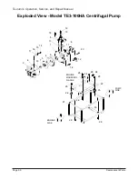
Install impeller on end of engine crankshaft (32) and rotate impeller (3) (clockwise) until
tight.
J.
Install packing (9) over raised lip on volute casing (4).
K.
Install volute casing (4). Align tab on volute casing (4) with raised alignment marks at the
0-degree position on casing cover (2). (The volute casing should also be constrained by
raised alignment marks at the 135-degree and 225-degree positions on the casing cover.)
L.
Install casing (1) over volute casing (4) and onto casing cover (2). Install four bolts (18).
M.
Install two brackets (25) over threaded end of cushion (24). Install two screws (30) through
bracket and into casing (1); do not tighten.
N.
Install nuts (26) on threaded end of cushions (24).
O.
Tighten screws (30) and nuts (26).
4-11 Replacement of Check Valve
A.
Remove three bolts (20), check valve (11), and suction case (6).
B.
Discard damaged check valve (11).
C.
Place the flat side of the replacement check valve (11) against the flat side of the suction
case (6). Position the check valve (11) with the valve pivot point in the top (zero degree
position).
D.
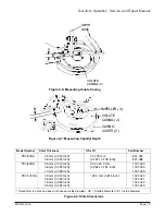
Align boltholes in replacement check valve (11) and suction case (6). (Refer to Figure 4-4
for the correct orientation).
E.
Attach suction case (6) to pump casing (1) using bolts (20)
Introduction
Page 23
Tsurumi’s Operation, Service, and Repair Manual


