5
NOTE!
Old oil should be entrusted to an oil disposal company in accordance with
local regulations.
The gasket and the O-ring for the oil filler plug must be replaced with a new
part at each oil inspection and change.
CAUTION!
In the event of inward leakage, the oil housing may be
pressurized. When removing the oil plug, hold a piece of cloth
over it to prevent oil from splashing.
CAUTION!
Before disassembling and reassembling the pump, be sure
that the power supply is disconnected, and remove the
cabtyre cable from the terminal board. To prevent serious
accidents, do not perform a conduction test during disassembly and
reassembly.
CAUTION!
Be sure to perform a trial operation when starting the pump
after a reassembly. If the pump was assembled improperly, it
may lead to abnormal operation, electrical shock, or water
damage.
CAUTION!
A worn impeller often has sharp edges. Take care not to cut
yourself on them.
Trouble shooting
CAUTION!
To prevent serious accidents, disconnect the power supply
before inspecting the pump.
Read this Operation Manual carefully before requesting repair. After re-inspecting
the pump, if it does not operate normally, contact your Tsurumi-dealer.
Pump fails to start
Pump is new or has been repaired and tested
• Check that voltage applied agree with rating plate.
• Check at pump cable free end (never open motor) insulation value of earth lead (over 20M
Ohm), and continuity of winding. On three phase motor check whether ohm values of
three windings are within ±10%.
Pump has been satisfactorily in use
• Same as above except that also impeller needs to be checked (stone, debris, rust between impeller
blades and suction cover after long disuse).
Pump starts but
stops immediately,
causing the motor
protector to actuate
• Motor windings or cable damaged. Do not open motor. Check as above.
• Impeller blocked or choked.
• If pump is new, wrong voltage or frequency.
• Voltage too low (most common cause); check supply voltage under load.
• If voltage is from diesel generator, inexact frequency.
• Wrong direction of rotation.
• Liquid of too high viscosity or density.
• Wrong setting of thermal overload unit.
The pump´s head
and pumping
volume is lower
• Wrong direction or rotation.
• Solid object (stone, etc.) in volute.
• Impeller severely damaged, or bearing damaged. Repair at once.
• Pump lying on its side and drawing a little air. High wear rate likely.
• Wrong direction of rotation.
• Piping resistance too high.
• Impeller worn, partially choked or severely narrowed by hard deposits.
• Strainer or inlet blocked.
• Pump draws air, or liquid is partly volatile or contains high level of gas in solution.
The pump
generates noise or
vibration
WARNING!
Never insert your hand or any other object into the inlet
opening on the underside of the pump casing when the pump
is connected to the power supply.
Before inspecting the pump casing, check that the pump has
been isolated from the power supply and cannot be energized.
Make sure that the pump is completely reassembled before putting into
operation again. Take care that bystanders keep a safe distance and avoid
contact with the water.
Removal of the suction cover (wear plate) and especially removal of the impeller,
and even more so the shaft sealing, must be left to a mechanic. Show him the
sectional view.
If the pump has a strange smell or appearance, have it cleaned professionally
before the mechanic touches it.
When reassembling, the mechanic will turn the impeller by hand to check that it
turns freely and that there is no ticking or grating noise from a bearing. Impellers
that are not of the vortex type, have a clearance with respect to the suction cover
(wear plate) of about 0,3 to 0,5 mm when new or repaired.
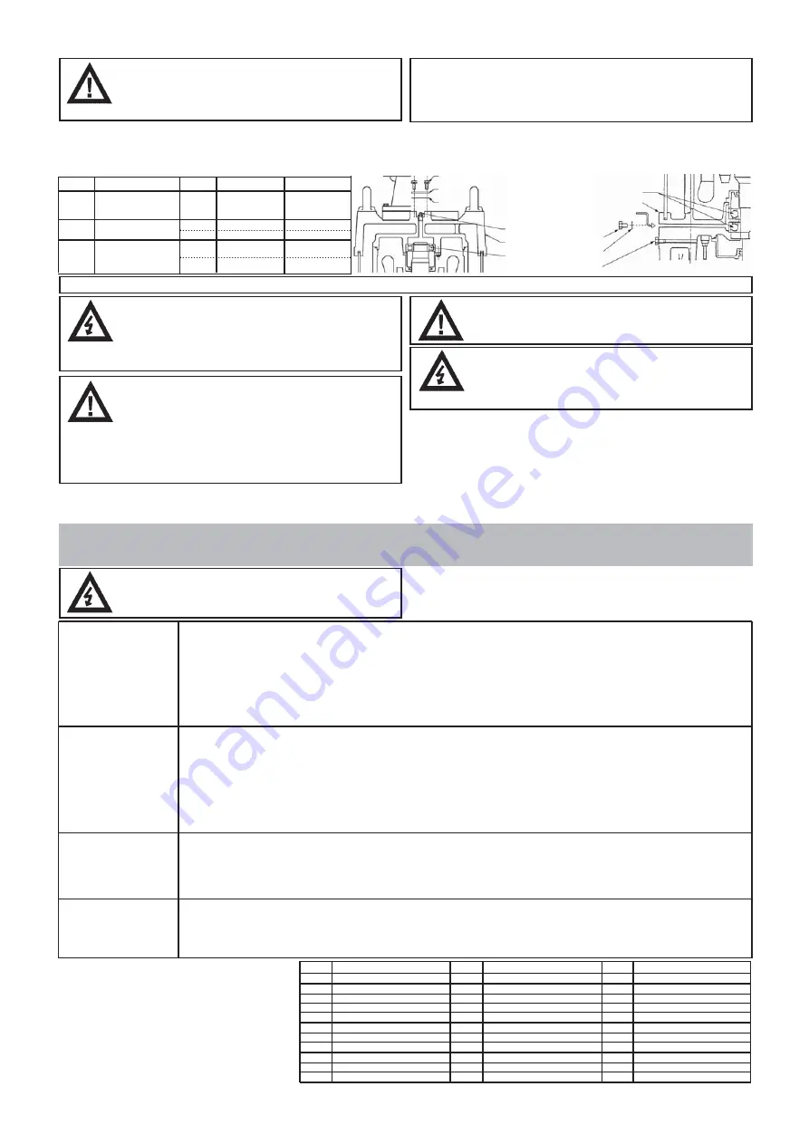
Bearing Grease (only LH with more than 55kW):
Refilling bearing grease (only LH with more than 55kW): Refilling of bearing grease should be done with upright standing position of the pump in accordance as
below. Remove a cover on center of motor bracket (fixed with two M6 hexagonal bolts) and grease plug {55-75kW (M25)}, {90-110kW (M12)} on the bearing housing
side for an upper and lower bearing respectively, and pour in grease from the grease nipple in accordance with the table as below and the drawing as shown on right
figure.
Note:
Replenishment period is every 3,000 hours, however it may vary due to operating condition.
Model
Bearing
Bearing Housing
Grease Inlet
Grease Plug
Hexagonal Bolt (M6)
Cover
Gasket
Grease Nipple
Motor Bracket
Bearing
O-Ring
Oil Plug
LH855
LH675
LH875
LH690
LH890
LH4110W
LH6110
LH8110
360g
100g
200g
370g
320g
60g
30g
60g
30g
60g
e.g. ENS GREASE
(Nippon Oil Co.)
e.g. Multinoc Delux 2
(Nippon Oil Co.)
e.g. RAREMAX SUPER
(Kyodo Yushi Co.,Ltd)
Initial quantity
Lower
Upper
Lower
Upper
Lower
Replenishment
kind of grease
Description of parts:
(see exploded view in appendix)
No.
1
2
3
4
5
6
7
8
9
10
11
No.
12
13
14
15
16
17
18
19
20
21
22
No.
23
24
25
26
27
28
29
30
31
32
33
Part Name
Hexagonal bolt
Spring washer
Mechanical seal
Oil ring
Rounded head screw
O-ring
Packing (Gasket)
Oil casing
Packing (Gasket)
Oil plug
Spring washer
Part Name
Hexagonal bolt
Shaft sleeve
Pump casing
Spring washer
Hexagonal bolt
O-ring
Labyrinth ring
Impeller adjusting washer
Impeller
Impeller thread protective cover
Hexagonal nut
Part Name
Impeller nut
Suction cover packing (gasket)
Suction cover
Spring washer
Hexagonal bolt
Spring washer
Stud bolt
Strainer
Bottom plate
Spring washer
Hexagonal nut
Replacing the impeller
Summary of Contents for GPN Series
Page 113: ......


