Ref#
QTY
Description
1
1
AXLE ASSY, RIGHT
2
1
AXLE ASSY, LEFT
3
1
HANDLE, RIGHT WITH GRIP
4
1
HANDLE, LEFT WITH GRIP
5
2
TIRE
6
4
U-BOLT FOR AXLE ASSY, SHORT
7
4
U-BOLT FOR HANDLE, LONG
8
4
HANDLE BRACKET
9
2
PLAIN WASHER FOR TIRE
10
2
COTTER PIN FOR TIRE
11
16
SPRING NUT
12
1
BOLT (M8-20)
` 13
1
NUT (M8) #3
WHEEL KIT
PGWK-200
FITS TSURUMI PUMPS & GENERATORS
Installation Instructions
Product Features
■
DESIGNED FOR LIFELONG
DURABILITY
■
STATE-OF-THE-ART ADJUSTABLE
SLIDING AXLE SYSTEM
■
FITS MOST GENERATOR SIZES AND
PUMPS
■
HIGHEST QUALITY METAL TUBING
■
ALL BRACKETS ARE PRECISION FIT
■
WIDE ANGLE HANDLE BARS FOR
EASY PORTABILITY
■
EASY COMFORTABLE GRIP
■
DOUBLE BALL BEARINGS ON EACH
AIRLESS TIRE
■
IMPOSSIBLE TO PUNCTURE
■
SMOOTH SLEEK DESIGN
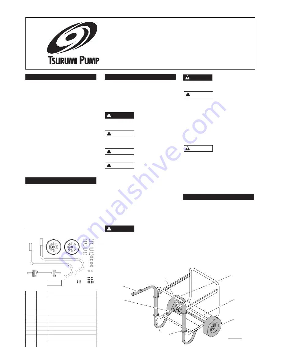
Unpacking
Upon receiving the wheel kit, it should be
inspected for damage or parts shortages
(See Fig. 1). If damage has occurred, file a
claim immediately with the carrier that
delivered the wheel kit.
If the manual is removed from the
packaging, do not lose or misplace.
Wheel Kit Parts Include
Safety Guidelines
This manual contains information that is
very important to know and understand.
This information is provided for SAFETY and
to PREVENT EQUIPMENT PROBLEMS.
To help recognize this information, observe
the following symbols.
Danger indicates an
imminently hazardous
situation which, if not avoided will result in
death or serious injury.
Warning indicates a
potentially hazardous
situation which, if not avoided COULD
result in death or injury.
Caution indicates a situ-
ation which, if not avoid-
ed, MAY result in minor or moderate injury.
Notice indicates impor-
tant information that if
not followed, may cause damage to
equipment.
1. Read product manual carefully prior to
wheel kit assembly to pump or
generator frame. Proper assembly and
installation to pump or generator pro-
vides carefree service.
2. Know the typical limitations and poten-
tial hazards associated with operating
and transporting gasoline engine driven
pump or generator equipment.
Never run the pumps or generator in an
enclosed area. Pump or generator should
only be operated in well ventilated areas
Engines produces exhaust gas containing
odorless and poisonous carbon monoxide
gas. Provide adequate ventilation and pre-
vent fire hazards, by
Operate the pump or
generator on a level
surface to prevent fuel spills.
Before installation,
ensure that there are
no fluids in the pump, generator or engine
prior to the wheel kit installation. Engine oil
and gasoline should be properly drained
from the engine. Ensure that there is no
gas in the fuel tank and/or carburetor bowl.
Drain all water from the pump housing.
Draining all fluids from the engine and
pump or generator will eliminate the
hazards from fluid spills. Keep children and
pets away from he installation work site.
Ensure that the wheel
kit contains the
appropriate parts (See Fig. 1) before
assembly to pump or generator. Assembly
of an incomplete wheel may cause damage
to the wheel kit, the pump, and generator.
This installation is best performed by two
people. A sturdy and stable block should
support the underside of the cart during
installation. A damaged or incomplete kit
may cause injury or property damage.
PERSONAL SAFETY
1. Wear safety glasses at all times when
installing wheel kit to pump or generator.
2. Keep work area clean, uncluttered and
properly lighted; replace all unused tools
and equipment.
3. Keep visitors at a safe distance from the
work area.
4. Make workshop childproof with padlocks,
master switches, and by removing starter
keys.
DANGER
WARNING
CAUTION
NOTICE
DANGER
DANGER
WARNING
CAUTION
Fig. 2
HANDLE
LEFT WITH GRIP
U-BOLT
FOR AXLE ASSY,
SHORT
TIRE
AXLE ASSY,
RIGHT/LEFT
TIRE
U-BOLT
FOR HANDLE,
LONG
HANDLE
RIGHT WITH GRIP
3
4
5
6 7
8
9
2
1
10
11
1213
Fig. 1


