- 8 -
Terminal
Description
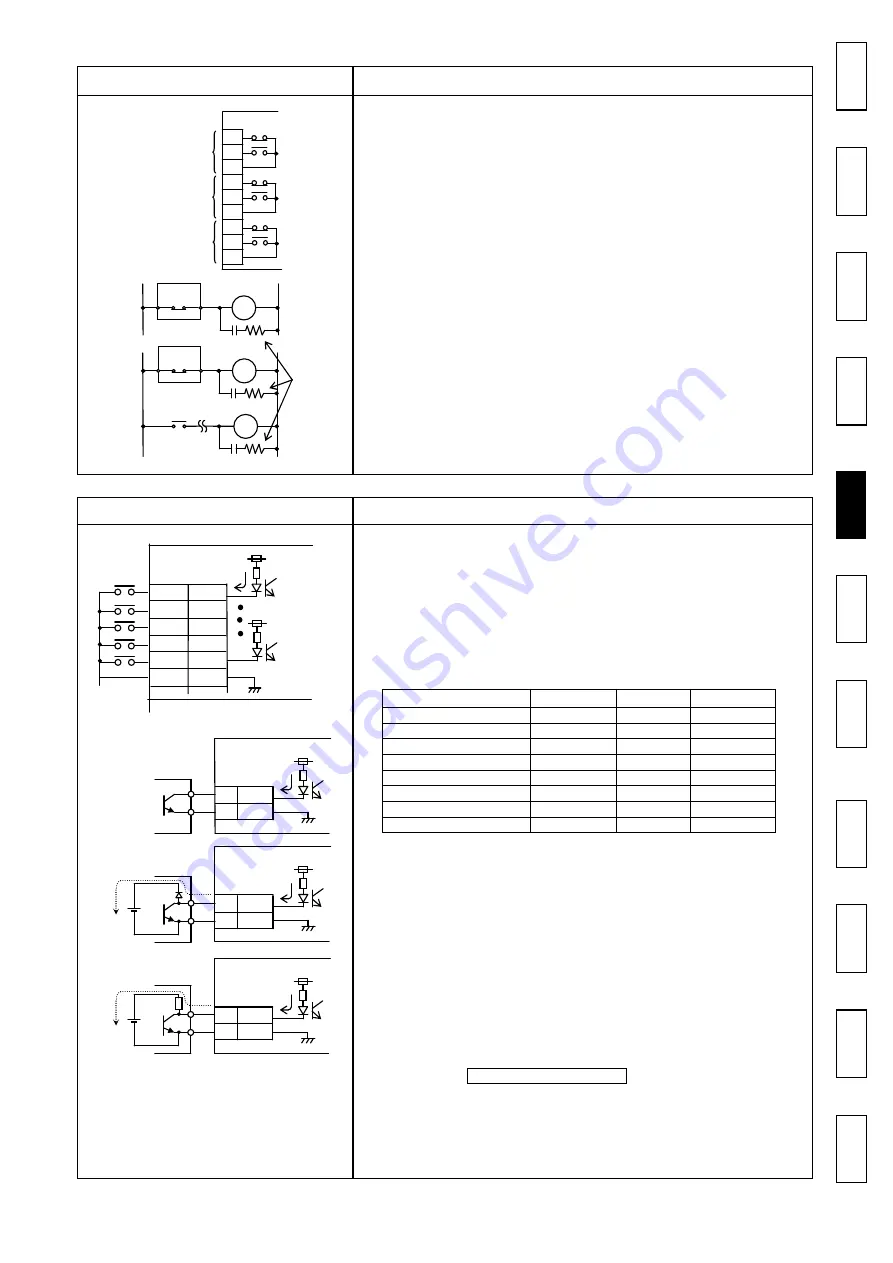
[Output relay]
● Output relay OUT1 (Terminals 4, 5, 6), OUT2
(Terminals 7, 8, 9), OUT3 (Terminals 13, 14, 15)
・
Output terminals used to notify external devices of
an alarm or overload condition. Three relay signals,
OUT1, OUT2, and OUT3 will be output.
Contact specification: 1c contact: 250 VAC, 0.5A
Contact specification: 1c contact: 250 VAC, 0.5A
Contact specification: 1c contact: 250 VAC, 0.5A
Contact specification: 1c contact: 250 VAC, 0.5A
(Inductive load cosφ = 0.4)
(Inductive load cosφ = 0.4)
(Inductive load cosφ = 0.4)
(Inductive load cosφ = 0.4)
Notes:
・
When an electromagnetic contactor is connected as shown
in the left figure
①
, limit the operating coil capacity to
less than 100 VA at power-on and to less than 10 VA
during retention. If an electromagnetic contactor with
larger capacity is connected, activate an auxiliary relay
with the output of the Shock Monitor as shown in the left
figure
②
, and then open/close the electromagnetic
contactor with the contact of the auxiliary relay.
・
As shown in the left figure, mount a CR absorber to
the coils of the electromagnetic contactor and
auxiliary relay to prevent noise generation.
・
When a sequencer photocoupler input which operates
with minute current (10 mA or less) is connected, activate
a relay for minute current with a relay output, and then
connect the contact of the relay for minute current to a
sequencer photocoupler input.
8.2 Connector CN1
Terminal
Description
[Contact input]
[Non-contact input]
● X1, X2, X3 (CN1 pin Nos. 1, 9, 2)
These terminals are used to externally switch preset
overload detection levels according to the load
condition of the equipment. The level can be switched
according to the load condition which varies depending
on the selected motor speed, material, process, etc.
Up to eight detection levels can be selected by using the
combination of the ON (short-circuit) and OFF (open)
statuses of terminals X1 to X3. Three individual settings
for OUT1 - OUT3 can be set for each selection No.
If a number larger than the value set for parameter
“5: Process” (No. of selected levels, refer to page 16)
is chosen, the selection will be [1].
● X4 (CN1 pin No. 10)
While the section between X4 and CM is
short-circuited, the load detection is stopped.
● X5 (CN1 pin No. 11)
When the section between X1 and CM is
short-circuited (turned ON), the integration of the
power starts.
Two integration methods are available: To integrate
the power while the section is turned ON; or to
integrate the power for the setting time after the
section is turned ON. This can be set with
parameter 3: Integration Time.
Note:
When setting [Non-contact input], be sure to use an
open collector signal shown in the left figure
①
.
Using
②
or
③
may cause malfunction due to a
detour circuit which may be created depending on the
condition of the power supply.
OUT1
OUT2
7
8
9
4
5
6
TSM4000
OUT3
14
13
15
Process No.
X1 - CM
X2 - CM
X3 - CM
Process [1]
OFF
OFF
OFF
Process [2]
ON
OFF
OFF
Process [3]
OFF
ON
OFF
Process [4]
ON
ON
OFF
Process [5]
OFF
OFF
ON
Process [6]
ON
OFF
ON
Process [7]
OFF
ON
ON
Process [8]
ON
ON
ON
①
②
X1
1
+12 V
TSM4000
CM
4
TSM4000
①
○
○
○
○
②
×
×
×
×
③
×
×
×
×
X1
1
CM
4
+12 V
X1
1
CM
4
+12 V
TSM4000
X1
1
X2
9
X3
2
10
4
X5
10 mA
+12 V
TSM4000
X4
11
CM
C
o
n
te
n
ts
U
s
a
g
e
/N
a
m
e
s
S
a
fe
ty
In
st
al
la
tio
n
/W
ir
in
g
T
er
m
in
a
ls
T
er
m
in
a
ls
T
er
m
in
a
ls
T
er
m
in
a
ls
C
on
n
ec
tio
n
O
p
e
r
a
ti
o
n
M
ai
n
te
n
an
ce
/In
sp
ec
tio
n
Sp
ec
ifi
ca
tio
ns
D
im
en
si
on
s
W
a
r
r
a
n
ty
CR
absorber
AR
MC
A R
T SM 4 0 0 0
EM contactor
Aux. relay
M C
T SM 4 0 0 0
EM contactor
Summary of Contents for TSM4000M2
Page 27: ...MEMO MEMO MEMO MEMO...


