background image

Adjusting the angles symmetry while turning the clamp


     Calibration is required to equalize the asymmetry of the angles while turning the clamp 

which may appear during transportation, as well as during long term use. Digital protractor is 

required for the calibration. The device should be firmly fixed on a flat surface.

1. 

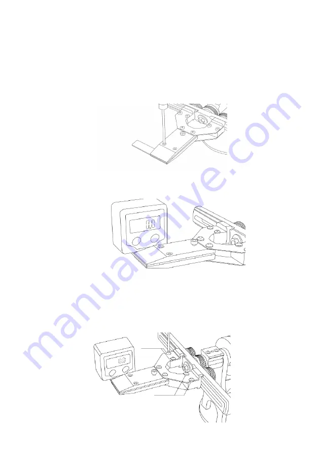
Set the calibration plate (14D) from the spare parts packet in the clamp. Jaws should 

remain parallel.

2.  Place the protractor on the plate along the axis of rotation of the clamp and reset.

3.  Turn the frame with clamp and make measurements. If the value is more than 0.3 °, loosen 

screws (1) and with arms adjust the angle of value equal to the previously measured 1/2 

difference. Holding this value, tighten the screws.

(1)


        (1)

17

Summary of Contents for K01RP

Page 1: ...Instruction s manual sharpening system TSPROF K01RP K03 Made in Russia...

Page 2: ......

Page 3: ...mping 9 Clamping of a knife with a tapered blade 10 Installation of an abrasive 10 Parking setting sharpening angle 11 Calibration 14 Calibration of horizontal frame 14 Turning Clamp angle calibration...

Page 4: ...220x330 Weight of the K01RP body without main units 1 68 kg Weight of the K03 body without main units 2 05 kg The length of the abrasive holder assembled 710mm The length of the abrasive used Min 150m...

Page 5: ...pcs 10 Single fillet clamp 1 pc 11 Smal universal table 1 pc 12 Double conical clamp 2 pcs 13 G Clamp 1 pc 14 A set of spare parts 1 pc A Wrench is L shaped hexagonal 2mm 1 pc B Wrench L shaped hexago...

Page 6: ...components Depends of the kit chosen 1 2 3 4 5 6 7 8 9 10 11 12 13 14 The scheme does not include accessories and abrasive stones A B C D E F G I 6...

Page 7: ...and to prevent corrosion periodically remove dust and dirt and wipe the places liable to the corrosion with a cloth slightly dampened with household oil Wipe dry with a tissue after For the lubricatio...

Page 8: ...surfaces of the G Clamp 14E from the spare parts package 2 Stick to the back side of the body 5 bumpers 14F from the spare parts package 3 Attach body to the table with G Clamp 1 Stick 5 bumpers 14F f...

Page 9: ...otary gear fixation effort Choose an effort so it doesn t flip during the process of sharpening 1 Assemble the abrasive holder and remove the stopper together with the amortization spring 2 Install th...

Page 10: ...the knife loosening the far 2 and near 1 clamping screws The example of a knife with a full flat grind Stick a piece of the leather or masking tape on the place of contact with the jaws in order to a...

Page 11: ...lamping screw is not enough replace it with a longer M4x16 14G from the spare parts package When you are working with the wholemilled clamps you need to tighten only one screw use 4mm hex key Try not...

Page 12: ...rasive Parking For convenience set the abrasive holder to the parking As it shown on the picture place parking boot on the parking disc Adjustment of the sharpening angle 1 Install a digital protracto...

Page 13: ...on of the angle adjust ment thumbsrew set the desired angle of sharpening 3 You can fix the angle of the sharpening with the help of a locking screw if necessary as shown in the picture below To do th...

Page 14: ...n the near stopper place the near edge of abrasive on the most far tip of the blade leaving about 1 5 2 cm 5 Move near limiter to the hub and tighten the thumbscrew Actions for the far limiter are sim...

Page 15: ...al It is not recommended to produce adjustments for the elimination of non essential deviations All adjustments should be performed on a flat solid surface Calibration of horizontal frame Option 1 1 P...

Page 16: ...ng the frame by hand tighten the lock nut Option 2 1 Place a ruler vertically touched to the edge of the frame and rest it in a flat table surface Make measurements on both sides 2 Holding the frame b...

Page 17: ...e device should be firmly fixed on a flat surface 1 Set the calibration plate 14D from the spare parts packet in the clamp Jaws should remain parallel 2 Place the protractor on the plate along the axi...

Page 18: ...et its value 2 Place the digital protractor on the ground for the protractor If the deviation is more than 0 3 slightly loosen the adjusting screw with an 2mm hex key While holding with the hand from...

Page 19: ...he Rack and Pinion lift 3 4 Adjustment of the Rack and Pinion lift movement 1 With the 2 mm hex wrench 14A from the spare parts package adjust the pinch screws 1 and 2 as it shown in the picture below...

Page 20: ...e exceeds 0 3 perform the adjustment 2 With the 2mm hex key 14A from the spare parts package install inclination of the plat form by adjustment screws Calibration of the in built gauge 1 Lower the abr...

Page 21: ...ules of operation use of the product for the purposes for which it is not intended Unskilled installation that resulted failure of the elements of the product or led to the poor performance of the pro...

Page 22: ...22 Deviation during the frame rotation Checked 20 Inspector SIGNATURE...

Page 23: ......

Page 24: ...Address 426065 Russia Izhevsk Str 10 let Oktybrya 60 office 405 Phone 1 877 63 88 248 US toll free E mail sales tsprof com Manufacturer Website tsprof com...

Reviews: