background image

P a g e

 | 

17 


PAM1 MK2  


User Handbook Issue 1 


2.5 

External Monitor Functionality  

 
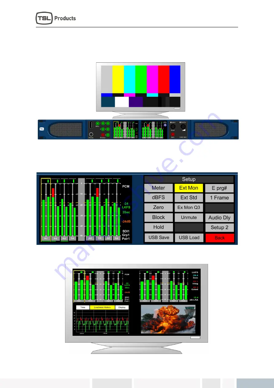
When an external monitor is first connected to PAM1 MK2 the screen will display a colour bar 
pattern signifying that the output is connected but not activated.  
 
.  


2.5.1 

Activating the External Monitor Output  

 
The External Monitor output is activated via the Setup menu. The menu is accessed by pressing 
the encoder, selecting 

Setup

 and then selecting 

Ext Mon 


The default view upon activation will appear as per the image below with bargraph displays in the 
upper quadrants of the image. 


Summary of Contents for PAM1 MK2

Page 1: ......

Page 2: ...earthed on installation Where appropriate the earth pin on the IEC mains inlet connector is connected to the metal frame of the equipment to 0 volts on the internal DC PSU and to signal ground unless...

Page 3: ...edure Please telephone 44 0 1628 676221 Fax 44 0 1682 676299 and ask for Customer Support detailing the model and serial number of the equipment who will provide a Returns Number This will enable us t...

Page 4: ...Rate Information 24 2 10 2 Dolby Metadata 25 2 10 3 Dolby E programme number selection 25 2 11 Monitoring using external loudspeakers 26 2 11 1 Discrete PCM 5 1 Using ALL Mode 26 2 11 2 Dolby E Dolby...

Page 5: ...in out details 53 3 1 Analogue XLR Connectors 53 3 2 AES XLR Connectors 53 3 3 Analogue Output Connector D25 Socket Pinout on unit Plug shown on mating cable 54 3 4 Analogue Input Connector D25 Socket...

Page 6: ...save recall Scroll To Hear top level bargraph navigation using rotary encoder Downmix of discreet multichannel audio to stereo for compatibility monitoring Multichannel audio outputs for external ster...

Page 7: ...P a g e 7 PAM1 MK2 User Handbook Issue 1 1 1 PAM1 MK2 Hookup Schematic...

Page 8: ...P a g e 8 PAM1 MK2 User Handbook Issue 1 1 2 PAM1 MK2 Front and Rear Panel...

Page 9: ...P a g e 9 PAM1 MK2 User Handbook Issue 1 1 3 PAM1 MK2 Front Panel Functions Quick Lookup...

Page 10: ...AM1 ships with a default 0dBu reference level set to 18 dBFs the default operating scale is EBU Digital A simple power up sequence may be used to alter the operating reference level to 20 dBFs with a...

Page 11: ...mple operation of PAM1 MK2 Press Shortcut to access a unique menu page which includes the most commonly used menu commands and features The USB port is used to save and load User Presets to a compatib...

Page 12: ...tcut menu provides instant access to the SDI1 SDI2 AES and Analogue sources The chosen input is routed instantly to the bargraph display and the Shortcut menu exited automatically 2 3 2 Display Mode S...

Page 13: ...his mode to a Hotkey switch for instant recall of the Data page Display Mode Loudness Histogram You can save this mode to a Hotkey switch for instant recall of the Loudness Histogram view Display Mode...

Page 14: ...abling the user to Downmix discrete 5 1 or 5 0 audio from any location within the 16 channels displayed Pressing and rotating the Downmix button also enables the user to scroll through the pair s sele...

Page 15: ...played to the external variable audio connectors in order to feed external active 5 1 speaker systems Pressing and rotating the ALL button also enables the user to scroll through the pair s selection...

Page 16: ...Histogram mode 2 4 2 Dim Cut Control The rotary volume control of PAM1 also features a push switch cut dim function Push the volume control once to cut the volume to internal speakers headphones and...

Page 17: ...signifying that the output is connected but not activated 2 5 1 Activating the External Monitor Output The External Monitor output is activated via the Setup menu The menu is accessed by pressing the...

Page 18: ...permanently display the bargraph information from the PAM1 left and right LCD screens and the lower right quadrant the currently active video signal image The lower right 3rd quadrant can be configure...

Page 19: ...hips with Hotkeys 1 4 pre programmed to instantly access SDI1 SDI2 AES and Analogue inputs Selecting these Hotkeys will directly route the selected input signal to the bargraph display Since these Hot...

Page 20: ...much more infrequently Where alternative means to select Monitoring functions are available they are described 2 8 1 Phase Reverse The Monitor Menu features a Phase Reverse button which enables the us...

Page 21: ...Up to four pairs may be mixed together simultaneously 2 8 5 Downmix Downmix Mode allows the operator to select an adjacent group of 3 audio pairs 6 audio channels and create a stereo Downmix Downmix M...

Page 22: ...ithout pressing to select a second non adjacent mono audio signal Once the selection is made the resultant selection is heard through the loudspeaker or headphone outputs with the first mono channel r...

Page 23: ...pair on the left screen as shown below In Top Level Mode the input bargraph display is shown on the right LCD display with a Dolby logo now superimposed below the decoded bargraph pair as shown The r...

Page 24: ...11 The image below shows an example of a 20 bit Dolby E signal embedded at line 507 This functionality is also extended to mixed sources If an AES source is selected for monitoring whilst a video sour...

Page 25: ...adata Page 1 Metadata Page 2 Page 2 Metadata fields include Video rate Dolby E Programme Description Dolby E Stream mode Dolby E Surround mode Dolby E LFE On Off Dolby E Mix Level Dolby E Room type Me...

Page 26: ...nd analogue outputs to variable level adjusted by the front panel volume control Stereo or 5 1 external loudspeakers can be connected see the application diagram in front of this Handbook 2 11 1 Discr...

Page 27: ...eaker channels are muted and only the Left and Right channels are active The 5 1 monitoring selections enable a user to solo individual surround sound signals to check the integrity of their audio The...

Page 28: ...Analogue De embedded AESand Analogue 5 1Audio from decoded source Muted De embedded AESand Analogue De embedded AESand Analogue 5 1Audio from selected channels DRC ALL Line or RF Muted De embedded AES...

Page 29: ...ame and number Source The selected input signal and channel Video The format of the selected video input signal or that of the most recently selected signal should an audio only source be routed to th...

Page 30: ...y as you choose them Having chosen your defaults move the yellow highlight box to SETUP2 but do not go into the lower menu Then press and hold the encoder without turning it for 15 seconds the screens...

Page 31: ...ur Mode Selection When set to Block mode the Peak parameter enables the user to choose to illuminate the indication between zero dBFs and the peak level in yellow 2 14 5 Hold The Hold parameter activa...

Page 32: ...teps up to a total value of 250ms may be selected The selection must be stored as part of the associated User Preset and is not set as part of the system default This allows the user to configure diff...

Page 33: ...erride the default speaker muting system designed to protect against hostile or unexpected audio signal conditions Use the encoder to select the UnMute button and push turn to select Data This will ov...

Page 34: ...verwritten Select the Hot Save button and push turn to lock The Hotkey function will now become disabled 2 14 15 GPI GPI functionality is described elsewhere within this handbook see Section 2 21 2 14...

Page 35: ...ux Mixer Aux Source Aux M S Aux Level Aux Mixer functionality is described elsewhere within this handbook see Section 2 19 2 15 Assign Matrix The Assign Matrix is intended for use in multichannel audi...

Page 36: ...s can be muted if they are not required as LFE in the example shown Once the Assign Matrix routing is completed and the matrix activated the following bargraph display is represented across the left a...

Page 37: ...ss implementation does not require the operator to listen to the audio components being measured as the location of the Hear Box and Loudness Cursor may be independent of one another Fixed and Dolby s...

Page 38: ...in the correct SMPTE channel order for 5 1 sound by selecting the channel components individually non SMPTE order 5 1 audio can be chosen and measured Unused channels can also be turned OFF for Stere...

Page 39: ...ines the point at which the Loudness value displayed changes from green to red The onscreen information is described below The Target Level can be set within a range of 13 to 30 or it can be defined b...

Page 40: ...means to integrate this could be to use studio or playout automation to start stop measurement via the GPI The Reset button discards any previously measured values enabling a new calculation to begin...

Page 41: ...ween the two time period displays three Integration modes and the Loudness Setup menu via the Loudness History button Any measured values which exceed the Target level are shown in red Over Target val...

Page 42: ...states ALL is the default condition and is used in normal operation By definition when Preset Standard is set to ALL the PAM1 operates as usual and is oblivious to changes to input signal types and fu...

Page 43: ...me on Group 1 Pair 1 the HD signal comprises a Dolby E signal on pair 2 with an encoded 5 1 programme The operator wants to hear the stereo programme when an SD signal is present and the Lt Rt Downmix...

Page 44: ...liary Input Mixer The Auxiliary Input Mixer AIM is intended for use in environments where users of PAM1 wear headphones during normal operation and need to listen to an additional audio input signal s...

Page 45: ...be mono so that the left and silent right inputs are summed together with equal signal sent to both left and right outputs Aux Level The Aux Level control enables the user to trim the level of the sel...

Page 46: ...d at the bottom of the screen Highlight and select Perform Update During an update the left hand LCD screen displays the progress of each stage of the installation on a bargraph with a scale 0 to 100...

Page 47: ...update procedure The Dolby CAT552 card may need to be reset in the event that it locks Select the CAT552 option from the Setup 2 menu and then reset the card 2 21 GPI Application The rear panel GPI co...

Page 48: ...I pin is driven low to allow an LED to be fed from the port This LED drive is briefly pulsed high at about 100Hz to allow the port to be read whilst it is driving The preset recall GPI s in Latching m...

Page 49: ...s User Preset Save and Recall functions can only be accessed via the Shortcut Menu Press Shortcut and the recall and save buttons can be seen at the bottom of the screen as shown below Pressing Preset...

Page 50: ...ve button via the Shortcut Menu The User Save menu automatically appears on the right hand screen Select the Clear button to delete the default or existing text and use the text fields to create a pre...

Page 51: ...new software releases In order for a storage device to be recognised by PAM1 it must contain a folder named in a recognised format The image below shows the default naming convention for a folder whic...

Page 52: ...ore the save procedure commences 2 23 5 SD Card USB Load Once a set of Hotkey and User Presets has been stored onto a USB storage device that device can be used to load the same presets onto other PAM...

Page 53: ...atech com and many others For unbalanced AES I O connectivity an optional BNC breakout cable CAB D25 BNC is available from TSL or your local reseller When used in conjunction with PAM1 DIP switch 2 AE...

Page 54: ...shown on mating cable D 25 SOCKET ON AMU AUDIO OUT PIN NO FUNCTION 1 A8 7 1 14 A8 7 1 2 Ground 15 A7 7 1 3 A7 7 1 16 Ground 4 A6 RS 17 A6 RS 5 Ground 18 A5 LS 6 A5 LS 19 Ground 7 A4 LFE 20 A4 LFE 8 Gr...

Page 55: ...ocket Pinout on unit Plug on mating cable D 25 SOCKET ON AMU AUDIO IN PIN NO FUNCTION 1 A6R 14 A6R 2 Ground 15 A6L 3 A6L 16 Ground 4 A5R 17 A5R 5 Ground 18 A5L 6 A5L 19 Ground 7 A4R 20 A4R 8 Ground 21...

Page 56: ...8 Out 4 21 Ch7 8 Out 4 9 N C 22 Ground 10 Ground 23 Ground 11 N C 24 Ground 12 Ground 25 Ground 13 Ground AES connectors may be wired using unbalanced terminations for SPDIF and 75R coaxial systems Op...

Page 57: ...ster operation D9 CONTROL 1 0V 6 0V 2 RX 7 RX 3 TX 8 TX 4 0V 9 0V 5 N C 3 8 DIP switch configuration functions SWITCH FUNCTION 1 Video aspect ratio 16 9 Up 4 3 Dn 2 AES Impedance 75R Up 110R Dn 3 Inte...

Page 58: ...the changes take effect Output analogue levels are adjustable over the following range 0dBm 0 775V into 600 i e 1mW power dissipation 0dBu 0 775V RMS PPM 4 Shipping condition 18 dB ref 0FS 0dBu outpu...

Page 59: ...ed Inputs AES 1 to 8 AES I O 25 way D type See elsewhere for details Input HD SDV 1 2 Connector Type BNC Standard 4 2 2 component with embedded 48Khz audio SMPTE 259M 292M and 424M Impedance 75ohm Lin...

Page 60: ...4 1080p 24 1035i 29 94 1080i 60 1080p 25 1080sf 30 1080P 50 1080p 29 97 1080sf 29 97 1080P 59 94 1080p 30 1080sf 25 1080P 60 1080i 25 1080sf 24 720p 50 1080i 24 94 1080sf 23 98 720p 59 94 1080i 30 720...

Page 61: ...AC coupled auto equalising with clock regeneration Impedance 75 return loss 15dB to 1 5GHz Standards SMPTE 259M C with embedded 48kHz audio per SMPTE 272M A SMPTE 292M with embedded 48kHz audio per S...

Page 62: ...o Eight analogue channels 4 stereo pairs that may be output from AES embedded audio or from decoded Dolby E D when the option is fitted Connector Type XLR one pair fixed or variable 25 way D type 4 st...

Reviews: