background image


26 

26

TTP-2410M/346M/644M 
TTP-246M Plus/344M Plus


Bar Code Printer Service Manua

l

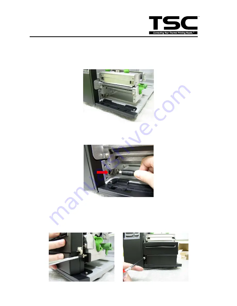
3.12 Cutter Module Installation (Option) 


1. Open the printer right side cover.


2. Refer to section 3.1 to remove the lower front panel. 


3. Plug the cutter mini DIN cable connector into the cutter/peel-off connector. The triangle 

mark on the connector must be at the upper side. 


4. Attach the cutter module to the front of the platen roller. Align the cutter bracket screw 

holes to the screw holes that fix the lower front panel. 


5. Fasten the 2 screws at the cutter bracket to fix the cutter module to the printer 

mechanism.


Summary of Contents for TTP-2410M

Page 1: ...TTP 2410M 346M 644M TTP 246M Plus 344M Plus SERVICE MANUAL THERMAL TRANSFER DIRECT THERMAL BAR CODE PRINTER ...

Page 2: ...ng Multi interface Board 17 3 5 Replacing the Main Board 18 3 6 Replacing the Platen Roller Assembly 19 3 7 Replacing the Stepping Motor 20 3 8 Replacing the Print head ASS Y 21 3 9 Replacing the Gap Black Mark Sensor Module 23 3 10 Replacing the Media Damper 24 3 11 Replacing the Ribbon Rewind Spindle 25 3 12 Cutter Module Installation Option 26 3 13 Peel off Kit Installation Option 27 3 14 Inter...

Page 3: ...M Plus 344M Plus Bar Code Printer Service Manual 1 FUNDAMENTAL OF THE SYSTEM 1 1 Overview Front View 1 LED indicators 2 LCD display 3 Front panel buttons 4 Paper exit chute 5 Lower front cover 6 Printer right side cover 1 2 3 4 6 5 ...

Page 4: ...ide plate 4 Print head 5 Platen roller 6 Print head release lever 7 Media guide bar 8 Label roll guard 9 Label supply spindle 10 Ribbon supply spindle 11 Damper 12 Label guide 13 Z axis mechanism adjustment knob 14 Print head pressure adjustment knob 15 Print head secure screw 16 Ribbon sensor 17 Media sensor 5 8 7 9 6 10 4 12 3 1 2 13 11 14 15 17 16 ...

Page 5: ...8 Ethernet interface 9 PS 2 interface 10 Power switch Note 1 SD card slot Ethernet interface and PS 2 interface are standard interfaces for TTP 2410M TTP 346M models but optional for TTP 246M Plus TTP 344M Plus models 2 GPIO interface card includes SD card slot Ethernet and PS 2 interfaces So GPIO interface is an factory option for TTP 2410M TTP 346M but a dealer option for TTP 246M Plus TTP 344M ...

Page 6: ...end Panasonic V1 0 V1 1 microSD 256 MB Transcend Panasonic V1 0 V1 1 microSD 512 MB Panasonic V1 0 V1 1 microSD 1 GB Transcend Panasonic V2 0 SDHC CLASS 4 microSD 4 GB Panasonic V2 0 SDHC CLASS 6 microSD 4 GB Transcend V1 0 V1 1 miniSD 128 MB Transcend Panasonic V1 0 V1 1 miniSD 256 MB Transcend Panasonic V1 0 V1 1 miniSD 512 MB Transcend Panasonic V1 0 V1 1 miniSD 1 GB Transcend Panasonic V2 0 SD...

Page 7: ...al 2 ELECTRONICS 2 1 Summary of Board Connectors Main board Connector Description 1 Centronics port connector 2 USB connector 3 RS 232C connector 4 LCD panel connector 5 Multi interface board connector GPIO interface board 6 Micro processor 1 2 3 4 5 6 7 9 10 8 11 12 16 13 14 15 ...

Page 8: ...d black mark sensor receiver A D 0 3 3V 3 Black mark sensor emitter 4 0 4 1V Emitter on 4 3 4 4V Emitter off 4 Gap sensor emitter 4 0 4 1V Emitter on 4 3 4 4V Emitter off 5 Power 5V Ribbon sensor connector 10 Pin Description Voltage 1 Ribbon sensor emitter 4 0 4 1V Emitter on 4 3 4 4V Emitter off 2 GND 0V 3 Ribbon sensor emitter power pin 5V 4 Ribbon sensor receiver A D 0 3 3V Ribbon encoder senso...

Page 9: ... direction 0V Cutter positive cut 5V Cutter negative cut 3 Cutter position sensor switch 0V Cutter stop 3 3V Cutter work 4 Peel sensor receiver A D 0 3 3V 5 Peel sensor emitter 4 0 4 1V Emitter on 4 3 4 4V Emitter off 6 Logic power 5V 7 GND 0V 8 Cutter power 24V 13 Power supply output 24V DC connector 14 GPIO interface power 24V DC connector 15 Print head connector 16 Stepping motor connector ...

Page 10: ...410M 346M 644M TTP 246M Plus 344M Plus Bar Code Printer Service Manual Multi interface board Connector Description Remark 1 Main board connector 2 SD card slot 3 Ethernet RJ 45 connector 4 PS 2 connector 1 3 2 4 ...

Page 11: ...s 344M Plus Bar Code Printer Service Manual GPIO with multi interface board Connector Description Remark 1 GPIO connector 2 Main board connector 3 SD card slot 4 Ethernet RJ 45 connector 5 PS 2 connector 6 GPIO power connector 2 1 4 3 5 6 ...

Page 12: ...In A low on this line indicates that there are valid data at the host When this pin is de asserted the ve clock edge should be used to shift the data into the device 2 9 Data 0 7 N A In Data Bus Single directional 10 Ack N A Out A low on this line indicates that there are valid data at the Device When this pin is de asserted the ve clock edge should be used to shift the data into the host 11 Busy ...

Page 13: ...14 Ground N A GND 15 No Defined N A N A 16 17 Ground N A GND Ground 18 No Defined N A N A 19 30 Ground N A GND Ground 31 No Defined N A N A 32 Error Fault N A Out A low set by the device indicates that the reverse data is available 33 35 Ground N A GND Ground 36 No Defined N A N A Ethernet PIN CONFIGURATION 1 Tx 2 Tx 3 Rx 4 N C 5 N C 6 Rx 7 N C 8 N C PS 2 PIN CONFIGURATION 1 KBD Clock 2 GND 3 KBD ...

Page 14: ...12 12 TTP 2410M 346M 644M TTP 246M Plus 344M Plus Bar Code Printer Service Manual GPIO ...

Page 15: ...ers and the Lower Front Panel 1 Remove two screws from rear of printer 2 Open printer right side cover and remove two screws then close the cover 3 Push the printer left side electronics cover toward the interface direction then take it out from the printer Please refer to the following pictures Screws Screws ...

Page 16: ...Manual 4 Remove 3 screws from each hinge Be careful the right side cover may fall out from the printer Take out the right side cover from the printer 5 Remove 2 screws to remove lower front panel 6 Reassemble the parts in the reverse procedures Electronics cover Screws Screws ...

Page 17: ...efer to section 3 1 to remove the electronics cover 2 Disconnect harness from the LCD panel module 3 Push two tabs to remove replace the LCD panel module 4 Remove five screws to remove replace LCD panel PCB ASS Y and LCD panel ASS Y 5 Reassemble the parts in the reverse procedures LCD panel module LCD panel PCB assembly ...

Page 18: ...to section 3 1 to remove the electronics cover 2 Disconnect all connectors on the power supply unit 3 Remove 2 TTP 2410M 346M 4 TTP 246M Plus 344 Plus screws and 2 cable ties TTP 2410M 346M TTP 246M Plus 344M Plus Connector Screw Cable tie 4 Remove Replace the power supply unit 5 Reassemble the parts in the reverse procedures ...

Page 19: ... interface Board 1 Refer to section 3 1 to remove the electronics cover 2 Remove 4 screws then take off the interface plate 3 Remove 2 screws 4 Replace the multi interface board 5 Reassemble the parts in the reverse procedures Screws Connector Screws Interface plate Multi interface board Copper pillar ...

Page 20: ...to remove the electronics cover Refer to section 3 4 to remove the multi interface board 2 Disconnect all connectors from the main board 3 Remove 5 screws from the main board Remove 2 copper pillars and 3 screws 4 Remove Replace the main board 5 Reassemble the parts in the reverse procedures Screws or copper pillars Screws Main board ...

Page 21: ...rinter right side cover 2 Disengage print head lift lever 3 Refer to section 3 1 to remove the lower front panel 4 Remove 2 screws from the platen holder 5 Take out the platen holder platen roller assembly and replace a new platen roller assembly 6 Reassemble the parts in the reverse procedures Screws Platen roller assembly Holder ...

Page 22: ...ng the Stepping Motor 1 Refer to section 3 1 to remove the electronics cover 2 Disconnect the stepping motor connector from the main board 3 Remove 2 screws on the stepping motor 4 Remove Replace the stepping motor 5 Reassemble the parts in the reverse procedures Stepping motor connector Screws ...

Page 23: ... connector from the print head ASS Y Please do not pull the cable to right and left side alternatively in order to disconnect it from the print head connector Please use the flat screw driver to push at the key in the middle of the connector When the connector becomes loose from the print head connector you can disconnect it TTP 2410M 346M TTP 246M Plus 344M Plus 6 Remove Replace the print head AS...

Page 24: ...4M Plus 8 Check the print head has been totally closed to the print mechanism before secure the print head by the previously removed thumbscrew 9 Reassemble the parts in the reverse procedures Note Please use the come with new print head secure screw to replace the print head assembly DO NOT use the original screw ...

Page 25: ...from the main board 3 Open the printer right side cover 4 Pull the media sensor module to the end of mechanism 5 At the bottom of the gap black mark sensor module there is a green plastic tab to latch the sensor module to the mechanism Push up the tab then pull out the gap black mark sensor module 6 Remove Replace the gap black mark sensor 7 Reassemble the parts in the reverse procedures Gap black...

Page 26: ...Code Printer Service Manual 3 10 Replacing the Media Damper 1 Open the printer right side cover 2 Remove the screw that fixes the damper to the mechanism 3 Remove Replace the media damper 4 Reassemble the parts in the reverse procedures Screw Media damper ...

Page 27: ...d Spindle 1 Refer to section 3 1 to remove the electronics cover 2 Remove 1 E ring 3 Remove the ribbon rewind spindle gear 4 Remove the E ring that fixes the spindle at the mechanism 5 Remove Replace the ribbon rewind spindle 6 Reassemble the parts in the reverse procedures E ring Ribbon rewind spindle gear E ring ...

Page 28: ...ower front panel 3 Plug the cutter mini DIN cable connector into the cutter peel off connector The triangle mark on the connector must be at the upper side 4 Attach the cutter module to the front of the platen roller Align the cutter bracket screw holes to the screw holes that fix the lower front panel 5 Fasten the 2 screws at the cutter bracket to fix the cutter module to the printer mechanism ...

Page 29: ...246M Plus 344M Plus Bar Code Printer Service Manual 3 13 Peel off Kit Installation Option 1 Refer to section 3 1 to remove the electronics cover 2 Fasten the screw 2 to fix the gear 1 Peel off kit parts list Gear 1 position Screw 2 ...

Page 30: ...gear 2 4 Put the bearing into the internal rewind hole 5 Open the printer right side cover 6 Remove the dustproof cover from the internal rewind hole and put the bearing into it 7 Insert the internal rewind into the hole Gear 2 position Internal rewind hole Left side Bearing Internal rewind hole Right side Bearing ...

Page 31: ... 344M Plus Bar Code Printer Service Manual 8 Use the E ring driver and hammer to fix the internal rewind by E ring How to assemble e ring a Put E ring into E ring driver b Put the E ring on roller niche c Use hammer to fix e ring and roller ...

Page 32: ... cable connector into the cutter peel off connector and place the cable in the cable cavity The triangle mark on the connector must be at the upper side 12 Attach the peel off module to the front of the platen roller Align the peel off module screw holes to the screw holes that fix the lower front panel 13 Fasten the 2 screws at the peel off module to fix the peel off module to the printer mechani...

Page 33: ...Printer Service Manual 3 14 Internal Rewinding Kit Installation Option 1 Refer to section 3 1 to remove the electronics cover 2 Fasten the screw 2 to fix the gear 1 3 Fasten the screw 2 to fix the gear 2 Internal rewinding kit parts list Gear 1 position Screw 2 ...

Page 34: ...aring into the internal rewind hole 5 Open the printer right side cover 6 Remove the dustproof cover from the internal rewind hole and put the bearing into it 7 Insert the internal rewind into the hole Gear 2 position Internal rewind hole Left side Bearing Internal rewind hole Right side Bearing ...

Page 35: ...ternal rewind by E ring Please refer to the section 3 13 for How to assemble e ring 9 Insert the gear with spring into the spindle and fix it with E ring 10 Refer to section 3 1 to remove the lower front panel 11 Fasten the 2 screws to fix the label redirect front panel to the printer mechanism Gear with spring E ring Screw Screw ...

Page 36: ......

Page 37: ...age No Ribbon Running out of ribbon The ribbon is installed incorrectly The ribbon sensor is not been well calibrated Supply a new ribbon roll Please refer to the steps in user s manual to reinstall the ribbon No Paper Running out of label The label is installed incorrectly Gap black mark sensor is not calibrated Supply a new label roll Please refer to the steps in user s manual to reinstall the l...

Page 38: ...45 connector amber LED is blinking Check if the printer gets the IP address when using DHCP mode Check if the IP address is correct when using the static IP address Wait a few seconds let the printer get the communication with the server then check the IP address setting again Chang a new cable Ribbon and media are not compatible Verify the ribbon inked side Reload the ribbon again Clean the print...

Page 39: ...here is dot missing in the pattern Change proper ribbon or proper label media Adjust the printhead pressure adjustment knob If the left side printout is too light please adjust the left side pressure adjustment knob to the higher index higher pressure If the pressure adjustment knob has been adjust to index 5 and the poor print quality is still at the left side of the printout please adjust the pr...

Page 40: ...right Skip labels when printing Label size is not specified properly Sensor sensitivity is not set properly The media sensor is covered with dust Check if label size is setup correctly Calibrate the sensor by Auto Gap or Manual Gap options Clear the GAP Black mark sensor by blower The printing position of small label is incorrect Media sensor sensitivity is not set properly Label size is incorrect...

Page 41: ...dark and turn on the printer again Wrinkle Problem Printhead pressure is incorrect Ribbon installation is incorrect Media installation is incorrect Print density is incorrect Media feeding is incorrect Please refer to the 5 2 chapter Please set the suitable density to have good print quality Make sure the label guide touch the edge of the media guide Gray line on the blank label The printhaed is d...

Page 42: ...is related to the media thickness print head pressure balance ribbon film characteristics print darkness setting etc In case the ribbon wrinkle happens please follow the instructions below to adjust the printer parts Adjustable Printer Parts Symptom 1 Wrinkle happens from label lower left to upper right direction ˊ 2 Wrinkle happens from label lower right to upper left direction ˋ Wrinkle Example ...

Page 43: ...te for step 3 Factory default setting the Z axis knob is rotated counter clockwise to the end of thread Turn the Z axis mechanism adjustment knob clockwise until you feel the knob touch the mechanism for the first adjustment If the wrinkle is still there please turn the Z axis mechanism adjustment knob clockwise about 1 4 circle each time for adjustment If the winkled direction is change from ˊ to...

Page 44: ...owing Printer Part Method Interval 1 Always turn off the printer before cleaning the print head 2 Allow the print head to cool for a minimum of one minute 3 Use a cotton swab Head cleaner pen and 100 ethanol to clean the print head surface Clean the print head when changing a new label roll Print Head Platen Roller 1 Turn the power off 2 Rotate the platen roller and wipe it thoroughly with 100 eth...

Page 45: ...r dampened cloth As needed Interior Brush or vacuum As needed Note z Do not touch printer head by hand If you touch it careless please use ethanol to clean it z Please use 100 Ethenol DO NOT use medical alcohol which may damage the printer head z Regularly clean the print head and supply sensors once change a new ribbon to keep printer performance and extend printer life ...

Page 46: ...rt number Camille 2008 3 7 Revise the Maintenance section Camille 2008 3 12 Revise the Troubleshooting section Camille 2008 3 21 1 Add print head harness TTP 644M part number 2 Update the LCD panel board assembly part no from 00LF to 10LF 3 Update the interface plate part no from 00LF to 10LF Camille 2008 4 29 1 Update the Multi interface board part no from 01LF to 11LF Camille 2008 6 23 1 Remove ...

Page 47: ...5 Sec 3 Beishin Rd Shindian City I Lan County 268 Taiwan R O C Taipei 231 Taiwan R O C TEL 886 3 990 6677 TEL 886 2 8913 1308 FAX 886 3 990 5577 FAX 886 2 8913 1808 Web site www tscprinters com E mail printer_sales tscprinters com tech_support tscprinters com TSC Auto ID Technology Co Ltd ...

Reviews: