background image


35 

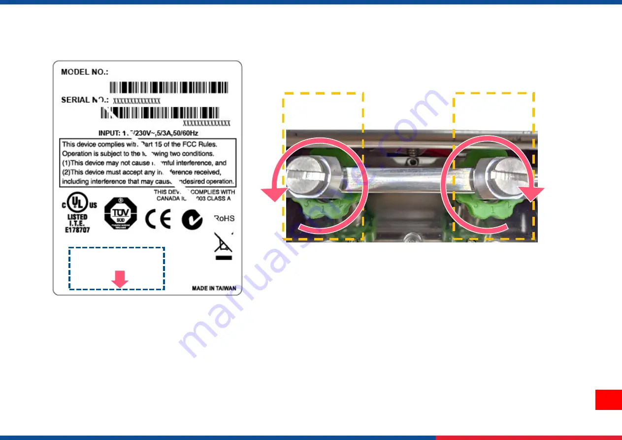
Wrinkle happens from label lower right to upper left direction 


Pressure level: 5>4>3>2>1 (5 is the highest) 


Step 1

 Decrease the left 

side’s pressure per level to check whether wrinkles is gone. adjustment knob. 


Step 2 

If right side pressure knob has been turned to level 1, but the wrinkle still exists, increase the left side pressure knob per 

level to check whether the wriknle has been disappeared or not. 

STEP 2 


STEP 1 

Feed Direction 

Summary of Contents for PEX-1120 Series

Page 1: ...r PEX1000 Series Industrial Barcode Printers User Manual Series Lists PEX1120 PEX1130 PEX1160 PEX1220 PEX1230 PEX1260 Thermal Transfer Direct Thermal ...

Page 2: ...from the Monotype Corporation Windows is a registered trademark of Microsoft Corporation All other trademarks are the property of their respective owners Information in this document is subject to change without notice and does not represent a commitment on the part of TSC Auto ID Technology Co No part of this manual may be reproduced or transmitted in any form or by any means for any purpose othe...

Page 3: ...s 4 1 3 Print Specifications 4 1 4 Ribbon Specifications 5 1 5 Media Specifications 5 2 Operation Overview 6 2 1 Unpacking and Inspection 6 2 2 Print Engine Orientation 7 2 3 Checking the Installation Space 8 2 4 Printer Overview 12 2 4 1 Front View 12 2 4 2 Interior View 13 2 4 3 Rear View 14 2 5 Operator Control 15 2 5 1 LED Indication and Keypads 15 3 Setup 18 ...

Page 4: ...nism Fine Adjustment to Avoid Ribbon Wrinkles 33 4 3 Suggestion of Ribbon Tension Adjustment 36 5 TSC Console 38 5 1 Start TSC Console 38 5 2 Setup Ethernet Interface 40 5 3 Set WiFi and Add to TSC Console Interface 42 5 4 Initialize the Printer WiFi Setting 45 5 5 Printer Function 46 5 6 Setting Post Print Action 47 6 LCD Menu Function 48 6 1 Enter the Menu 48 6 2 Menu Overview 49 6 3 Setting 50 ...

Page 5: ...e 57 6 5 1 Serial Comm 58 6 5 2 Ehernet 59 6 5 3 Wi Fi 60 6 5 4 Bluetooth 61 6 5 5 GPIO 62 6 6 Advanced 67 6 7 File Manager 69 6 8 Diagnostic 70 6 9 Favorites 71 7 TroubleShooting 73 8 Maintenance 76 9 Angency Compliance and Approvals 78 10 Revise History 84 ...

Page 6: ...n easy to use color display The PEX offers simple integration into both new and existing label application installations It is ideal for manufacturing and logistic applications where high speed and high demand label printing is required This document provides an easy reference for operating the PEX 1000 series TSC printers include the Windows labeling software for creating your label template For ...

Page 7: ...SD card reader for memory expansion up to 32GB Interface RS 232 Max 115 200 bps USB 2 0 High speed mode Internal Ethernet 10 100 Mbps USB host Front side connecting USB storage device GPIO Applicator interface with DB15F connector 5V I O Parallel Sensors Gap transmissive sensor Position adjustable 15mm 98mm Black mark reflective sensor Position adjustable 15mm 92mm Ribbon end sensor Ribbon encoder...

Page 8: ... 2D bar code CODABLOCK F mode DataMatrix Maxicode Micro PDF 417 Aztec MicroPDF417 QR code RSS Barcode GS1 Databar Font bar code rotation 0 90 180 270 degree Command set TSPL EZD Others Standard for real time clock Standard for buzzer Print head pressure force pressure location adjustable Heater element damage detection Clean print head warning 1 1 2 Printer Optional Features The printer offers the...

Page 9: ...g Storage 40 60 C 40 140 F 10 90 non condensing 1 3 Print Specifications Print Specifications PEX 1120 PEX 1220 PEX 1130 PEX 1230 PEX 1160 PEX 1260 Print head resolution dots per inch mm 203 dots inch 8 dots mm 300 dots inch 12 dots mm 600 dots inch 24 dots mm Printing method Thermal transfer or direct thermal Dot size width x length 0 125 x 0 125 mm 1 mm 8 dots 0 084 x 0 084 mm 1 mm 12 dots 0 042...

Page 10: ... type Continuous die cut black mark external fan fold notch Media width 20 mm 114 mm 0 78 4 49 Media thickness 0 076 mm 0 305 mm 2 99 12 01 mil Label length 5 mm Label length peeler mode Factory option of media sensor for 5mm 152mm Gap sensor only with fixed position of the sensor System integrator need to notice the design of Take Label Sensor to fit the label position of the small size of the la...

Page 11: ...upon receiving the bar code printer Please retain the packaging materials in case you need to reship the printer Unpacking the printer the following items are included in the carton 1 Printer unit 1 Quick installation guide 1 Power cord 1 USB interface cable 1 CD unit If any parts are missing please contact the Customer Service Department of your purchased reseller or distributor ...

Page 12: ... 1160 series PEX 1220 PEX 1230 PEX 1260 series Left hand model Right hand model Note This document is going to show the components inside the media compartment of a left hand print engine A right hand unit contains a mirror image of those components Familiarize yourself with these components before continuing with the print engine setup procedure ...

Page 13: ...8 2 3 Checking the Installation Space Please check the space for mounting the print engine into an applicator Please refer to the dimensions in this section ...

Page 14: ...9 ...

Page 15: ...10 ...

Page 16: ...11 ...

Page 17: ... Soft keys 2 Power switch 3 LCD display 4 Wi Fi antenna option 5 USB host 6 LED indicator 7 Navigational keys 8 Media view window 9 Print engine cover 2 4 Printer Overview 2 4 1 Front View 2 4 1 6 7 3 8 9 5 ...

Page 18: ...pressure adjustment knobs 4 Print head release lever 5 Print engine cover open sensor 6 Ribbon supply spindle 7 Label guide bar release lever 8 Media sensor position adjustment knob 9 Platen roller 10 Print head 11 Media sensor Black mark Blue Gap Whilte 12 Label guide 12 7 6 1 2 3 4 8 9 10 11 5 ...

Page 19: ...h DB15F connector 5V I O 2 RS 232C interface 3 Ethernet interface 4 USB interface 5 Power cord socket 6 Centronics interface 7 Micro SD card socket Note The interface picture here is for reference only Please refer to the product specification for the interfaces availability ...

Page 20: ...15 2 5 Operator Control LED Printer status Printer mode Firmware version Icons Navigation Keys Ethernet Wi Fi IP Soft Keys ...

Page 21: ...is paused Amber System is clearing data Red Solid Printer head open cutter error Flash Printing error such as paper empty paper jam ribbon empty or memory error etc Keys Keypads form Item name Function Soft keys The display will show the function for left and right key The meaning of the soft keys will depend on the UI screen Navigational keys Select Navigate ...

Page 22: ...rnet is connected Bluetooth device is ready option Remaining amount of ribbon m Pending documents in the printer Security lock Print head cleaning notice Print engine cover open Enter the menu Enter cursor be marked in green located option Feed button advance one label ...

Page 23: ... off 3 Connect the print engine to the computer with the provided USB cable or available connections 4 Plug the power cord into the AC power cord socket at the rear of the print engine and then plug the power cord into a properly grounded power outlet Note Please switch OFF the printer before plugging in the power cord to printer power jack ...

Page 24: ...9 3 2 Loading the Ribbon 1 Open the meida cover Left hand model Right hand model 2 Install the ribbon and paper core onto ribbon supply spindle and ribbon rewind spindle Left hand model Right hand model ...

Page 25: ...e ribbon and paper core onto ribbon supply spindle and ribbon rewind spindle Left hand model Right hand model 4 Thread ribbon above the ribbon guide bar and through ribbon sensor slot Left hand model Right hand model ...

Page 26: ...e counterclockwise roughly 3 5 circles until ribbon is smooth properly stretched and wrinkle free Left hand model Right hand model 6 Close the print head mechanism by pushing the print head release lever Left hand model Right hand model ...

Page 27: ...22 Ribbon Loading Path Left hand model Ink coated outside wound Ink coated inside wound Right hand model Ink coated outside wound Ink coated inside wound ...

Page 28: ...pen the meida cover Note There is no media supply spindle for standard model Left hand model Right hand model 2 Open the print head release lever and label guide bar release lever for loading media Left hand model Right hand model ...

Page 29: ...e of the label through the media guide bar pass media sensor and place the leading edge onto the platen roller Left hand model Right hand model 4 Adjust the rear label guide to fit the label width Left hand model Right hand model ...

Page 30: ...eft hand model Right hand model 6 Move the media sensor by adjusting the media sensor position adjustment knob make sure the sensor is able to sense the media Left hand model Right hand model GAP White Black mark Blue Print head GAP White Black mark Blue Print head ...

Page 31: ... label guide bar release lever 8 Set media sensor type and calibrate the selected sensor Note Please calibrate the gap black mark sensor when changing media Left hand model Right hand model Media Loading Path Left hand model Right hand model ...

Page 32: ...27 3 4 Loading Media in Peel off Mode Option 1 Open the meida cover and refer chp 3 3 to load the media Note There is no media supply spindle for standard model Left hand model Right hand model ...

Page 33: ...lever and label guide bar release lever to thread the label through the front of the print engine and remove several labels Left hand model Right hand model 3 Open the peel off roller release lever Left hand model Right hand model ...

Page 34: ...29 4 Feed the leading edge of liner through the peel off roller Left hand model Right hand model 5 Press the roller to close the peel off roller release lever Left hand model Right hand model ...

Page 35: ...30 6 Close print head release lever and label guide bar release lever and press Feed button to test Left hand model Right hand model Media Loading Path for Peel off Mode Left hand model Right hand model ...

Page 36: ... inbound of the printer mechanism different media width requires the different pressure Users can try which level can meet their expectation Pressure level 5 4 3 2 1 5 is the highest If the label width is 4 adjust both print head pressure to the same level If the label is less than 2 wide increase the pressure of left adjustment knob and decrease the right side pressure ...

Page 37: ... ribbon is aligned to the inbound of the printer mechanism different ribbon or media widths require different ribbon tension to print correctly Therefore it may require to adjust the ribbon tension adjustment knob to avoid wrinkle and get the best print quality Tension level 1 2 3 Default 1 1 is the highest ...

Page 38: ...n Wrinkles Ribbon wrinkle is related to the media width thickness print head pressure balance ribbon film characteristics print darkness setting etc In case the ribbon wrinkle happens please follow the instructions below to adjust the printer parts ...

Page 39: ...ease the right side s pressure per level to check whether wrinkles is gone adjustment knob Step 2 If right side pressure knob has been turned to level 1 but the wrinkle still exists increase the left side pressure knob per level to check whether the wriknle has been disappeared or not STEP 1 STEP 1 STEP 2 Feed Direction ...

Page 40: ...Decrease the left side s pressure per level to check whether wrinkles is gone adjustment knob Step 2 If right side pressure knob has been turned to level 1 but the wrinkle still exists increase the left side pressure knob per level to check whether the wriknle has been disappeared or not STEP 2 STEP 1 Feed Direction ...

Page 41: ...djustment For 4 width ribbon If the ribbon width is 4 adjust both ribbon tension adjustment knobs to the 1 on ribbon supply rewind spindles Factory default ribbon tension is 1 Ribbon Supply Spindle Tension 1 Ribbon Rewind Spindle Tension 1 ...

Page 42: ...the 2 on ribbon supply rewind spindles For 2 width ribbon If the ribbon width is 2 adjust both ribbon tension adjustment knobs to the 3 on ribbon supply rewind spindles Ribbon Supply Spindle Tension 2 Ribbon Rewind Spindle Tension 2 Ribbon Rewind Spindle Tension 3 Ribbon Supply Spindle Tension 3 ...

Page 43: ...aphics deploy fonts graphics label templates or upgrade the firmware to the group of printers and send additional commands to printers at the same time Printer firmware version before A2 12 will only use 9100 Port as command port Printer firmware after A2 12 will use 6101 Port as command port 5 1 Start TSC Console 1 Double click TSC Console icon to start the software 2 Manually add the devices by ...

Page 44: ... 3 Select the current interface of the printer 4 The printer will be added to TSC Console s interface 5 Select the printer and set the settings For more information please refer to TSC Console User Manual ...

Page 45: ...40 5 2 Setup Ethernet Interface Use USB or COM to establish the interface on TSC Console Double click to enter the Printer Configuration Page Click Ethernet tab Check the IP Address ...

Page 46: ... Add Printer on the top left of the window Choose Network Key in the IP Address Click Discover to establish the Ehternet interface The notification will pop up Click OK to close the window The Ethernert interface will be shown on TSC Console ...

Page 47: ... to TSC Console Interface Use USB or COM Port to set up the interface refer to chp 5 1 Double click to enter the printer configuration page Click Get to receive printer s information Click Wi Fi to the wi fi setting page 1 2 ...

Page 48: ...Port field For WPA Enterprise I Fill in the SSID II Select the Encryption option to WPA2 Enterprise III Select DHCP to ON For OFF option please fill in the IP Address Subnet Mask and Gateway IV Select the EAP Type option For EAP TLS option please upload the CA and Key for mutual authentication integrity protected cipher suite negotiation and key exchange between two endpoints V After setting click...

Page 49: ...wn within about 5 15 seconds after printer turn on If not please refer to steps below to initialize the printer Wi Fi module settings then to setup it again Remove the cable between the computer and the printer Go to main page click Add Printer to add the printer via Network Select the printer and enter the setting page by double clicking the printer Click the Print Test Page button to print the t...

Page 50: ...Initialize the Printer WiFi Setting 1 Return to the main page of TSC Console 2 Click Functions to expand the page 3 Click Wi Fi Default to initialize the printer Wi Fi module setting to factory default setting ...

Page 51: ... on PC Factory Default Initialize the printer to default settings Reset Printer Reboot printer Print Test Page Print test page according to the specified label size and sensor type Configuration Page Print printer configurations Dump Text Activate the printer to dump mode Ignore AUTO BAS Ignore AUTO BAS file when printer boot up Exit Line Mode Exit the line mode to page mode Enter Line Mode Leave ...

Page 52: ...er finishing the calibration Follow below procedure to set the post action for the printing Refer Chp 5 1 to Connect the printer with TSC Console Double click the printer The Printer Configuration Page will pop up Click Get to load information Go to Common Tab Find Post Print Action Select the mode depends on users application Click Set ...

Page 53: ...left side soft key means to enter the Menu 2 Use the navigational keys to select the icon be marked in green and press the right soft key means to enter the selected item Press left soft key means to return to previous page Left soft Keys Navigational Keys ...

Page 54: ...owing sections for more details Setting To set up the printer settings for TSPL ZPL2 File Manager To check and manage printer s memory storage Advanced To set LCD initialization cutter type etc Sensor To calibrate the selected media sensor Interface To set the printer interface settings Diagnostic To check printer and help users to troubleshoot the problems ...

Page 55: ...50 6 3 Setting Tap the Command Set on LCD to switch between TSPL and ZPL2 Command Set can also be activated by Navigational Keys ...

Page 56: ...egory can set up the printer settings for TSPL Setting TSPL Speed Slew Speed Back Speed Density Direction Print mode Batch Mode Applicator Stream Rewinder Mode Offset Shift X Shift Y Reference X Reference Y Code Page Country ...

Page 57: ...g process label will be fed to the tear plate location Applicator The printer prints a label when it receives a signal from the applicator Stream The print engine prints a batch of labels with backfeed occurring only at the start and end of the batch instead of between individual labels Rewinder Mode Enable the label rewinder mode Batch Mode Offset Adjust media stop location Available value settin...

Page 58: ... Speed Tear Off Print Mode Tear Off Applicator Stream Rewind Print Width List Fonts List Images List Formats List Setup Control Prefix Format Prefix Delimiter Char Media Power Up Feed Calibration Length No Motion Head Close Feed Calibration Length No Motion Label Top Left Position Reprint Mode Enabled Disabled Format Convert ...

Page 59: ...n it receives a signal from the applicator Stream The print engine prints a batch of labels with backfeed occurring only at the start and end of the batch instead of between individual labels Rewind Enable the label rewinder mode Tear Off Print Width Set the print width Available setting range 2 999 dots 812 List Fonts Print the current fonts list from the memory devices to the label N A List Imag...

Page 60: ...inter determine length and feed label No Motion Printer will not move media No Motion Label Top Adjust print position vertically on the label Value range 120 to 120 dots 0 Left Position Adjust print position horizontally on the label Value range 9999 to 9999 dots 0 Reprint Mode Reprint the last label by pressing button on printer s control panel Disabled Format Convert Select the bitmap scaling fa...

Page 61: ...ease use Manual function to set the paper length and gap bline size to complete the calibration setting N A Threshold Detect Set sensor sensitivity in fixed or auto Auto Maximum Length Set the maximum length for label calibration 254 mm Advanced Set the minimum paper length and maximum gap bline length for auto calibratIon 0 mm Menu Sensor Auto Calibration Gap Black Mark Continuous Preprint Manual...

Page 62: ...57 6 5 Interface Interface can set the printer interface settings Menu Interface Serial Ethernet Wi Fi Bluetooth GPIO ...

Page 63: ... Rate Set the RS 232 baud rate 9600 Parity Set the RS 232 parity None Data Bits Set the RS 232 Data Bits 8 Stop Bit s Set RS 232 Stop Bits 1 Menu Interface Serial Baud Rate 1200 bps 2400 bps 4800 bps 9600 bps 19200 bps 38400 bps 57600 bps 115200 bps Parity None Odd Even Data Bits 7 8 Stop Bit s 1 2 ...

Page 64: ... reset the Ethernet module Item Description Default Status Check the Ethernet IP address and MAC setting status N A Config DHCP On or OFF the DHCP Dynamic Host Configuration Protocol network protocol Static IP Use this menu to set the printer s IP address subnet mask and gateway DHCP Menu Interface Ethernet Status Config ...

Page 65: ...C setting status etc N A Config DHCP ON OFF the DHCP Dynamic Host Configuration Protocol networkprotocol Static IP Set the printer s IP address subnet mask and gateway DHCP SSID Set Wi Fi SSID N A Security Set Wi Fi security Open Password Set Wi Fi password N A Menu Interface Wi Fi Status Config SSID Security Password ...

Page 66: ...inter Bluetooth settings Item Description Default Status Check the Bluetooth status N A Local Name Set the local name for Bluetooth RF BHS Ping Code Set the local ping code for Bluetooth 0000 Menu Interface Bluetooth Status Local Name Ping Code ...

Page 67: ...tion is used to set the print engine GPIO settings Applicator interface with DB15F connector 5V I O Menu Interface GPIO Applicator Port Start Print SIG Error On Pause Ribbon Low Mode Ribbon Low Output Backfeed Reprint Mode ...

Page 68: ...NT END Selections Description Off The applicator port is off Mode 1 Label format sent Label format processed Waiting for start print signal Label prints Ready for next label Data ready Pin 14 GPO_6 Not ready Ready Print start Pin 3 GPI_1 Do not start Start Print End Pin 11 GPO_3 Do not end End Off ...

Page 69: ... Ready for next label Data ready Pin 14 GPO_6 Not ready Ready Print start Pin 3 GPI_1 Do not start Start Print End Pin 11 GPO_3 Do not end End Mode 3 Label format sent Label format processed Waiting for start print signal Label prints Ready for next label Data ready Pin 14 GPO_6 Not ready Ready ...

Page 70: ...n 11 GPO_3 Do not end End Mode 4 Label format sent Label format processed Waiting for start print signal Lab el prints Ready for next label Data ready Pin 14 GPO_6 Not ready Ready Print start Pin 3 GPI_1 Do not start Start Print End Pin 11 GPO_3 Do not End End ...

Page 71: ... printer is paused the error signal GPO_2 is LOW Enable Ribbon Low Mode When this option is enabled and the printer is Low Ribbon GPO_1 the printer will generate a warning Enable Ribbon Low Output When the Ribbon Low Mode feature is enabled this parameter determines if the output signal on Pin 9 GPO_1 is HIGH or LOW Active High Backfeed This determines the timing of pullback Default Reprint Mode W...

Page 72: ...s N A Display Brightness Set the brightness for display Range 0 100 50 Touchscreen Calibration Calibrate the touchscreen for best result N A Menu Advanced Language Printer Information Initialization Display Brightness Touchscreen Calibration Date Time Date Format Date Time Format Time Security Menu Lock Menu Password MyMenu Lock MyMenu Password Cutter Type Media Low Warning Ribbon Low Warning Prin...

Page 73: ...ad status and to set the settings for print head care Warning Enable disable the print head clean warning If enable this feature once print head has been reached the setting mileage then the warning icon will be shown on printer UI for reminding user to clean the print head The default setting is disable Reset Counter Reset the print head clean warning mileage after cleaning print head Interval Th...

Page 74: ...File Manager File Manager is used to check the printer available memory show the files list delete the files or run the files that saved in the printer DRAM Flash Card memory Menu File Manager DRAM FLASH CARD ...

Page 75: ...ump mode all characters will be printed in 2 columns The left side characters are received from your system and right side data are the corresponding hexadecimal value of the characters It allows users or engineers to verify and debug the program Dump mode requires 4 wide paper width Print Head Check print head s temperature and bad dots Display Check LCD s color state Sensor Check sensors intensi...

Page 76: ...stomized menu list You can organize the commonly used setting options to the Favorites list Enter Favorites List 1 Press and hold the left side soft key on Ready mode to enter Favorites Default No items in the list Press and hold left soft keys ...

Page 77: ...s window pops up Select Yes to add the item to Favorites list Delete Items From Favorite 2 Select one option item and press and hold the right soft key until Deltete Favorites window pops up Select Yes to remove the item from Favorites list Press and hold the right soft key Press and hold the right soft key ...

Page 78: ...f there is a command PRINT at the end of the file and there must have CRLF at the end of each command line No print on the label Label or ribbon is loaded not correctly Use wrong type paper or ribbon Follow the instructions in loading the media and ribbon Ribbon and media are not compatible Verify the ribbon inked side The print density setting is incorrect No Ribbon Running out of ribbon The ribb...

Page 79: ...el size Gray line on the blank label The print head is dirty The platen roller is dirty Clean the print head Clean the platen roller Please refer to chapter 8 Irregular printing The printer is in Hex Dump mode The RS 232 setting is incorrect Turn off and on the printer to skip the dump mode Re set the RS 232 setting Label feeding is not stable skew when printing The media guide does not touch the ...

Page 80: ...t X in LCD menu is incorrect Set the correct label size Press Menu Setting Shift X to fine tune the parameter of Shift X The printing position of small label is incorrect Media sensor sensitivity is not set properly Label size is incorrect The parameter Shift Y in the LCD menu is incorrect The vertical offset setting in the driver is incorrect Calibrate the sensor sensitivity again Set the correct...

Page 81: ...ectrostatic damage Do not wear rings or other metallic objects while cleaning any interior area of the printer Use only the cleaning agents recommended in this document Use of other agents may damage the printer and void its warranty Do not spray or drip liquid cleaning solutions directly into the printer Apply the solution on a clean lint free cloth and then apply the dampened cloth to the printe...

Page 82: ...printer II Rotate the platen roller and wipe it thoroughly with the lint free 99 Isopropyl Alcohol Clean the platen roller when changing a new label roll Peel Bar Use the lint free cloth with 99 Isopropyl Alcohol to wipe it As needed Sensor Use brush with soft non metallic bristles or a vacuum cleaner to remove paper dust Clean upper and lower media sensors to ensure reliable Top of Form and Paper...

Page 83: ...and if not installed and used in accordance with the manufacturer s instruction manual may cause harmful interference with radio communications Operation of this equipment in a residential area is likely to cause harmful interference in which case you will be required to correct the interference at your own expense This Class A digital apparatus complies with Canadian ICES 003 Cet appareil numériq...

Page 84: ...d easily accessible 5 The unit must be protected against moisture 6 Ensure the stability when installing the device Tipping or dropping could cause damage 7 Make sure to follow the correct power rating and power type indicated on marking label provided by manufacture 8 Please refer to user manual for maximum operation ambient temperature WARNING Hazardous moving parts keep fingers and other body p...

Page 85: ...labels ribbons or to repair After completing the steps please close the media cover first and then turn on the power to start printing CAUTION Any changes or modifications not expressly approved by the grantee of this device could void the user s authority to operate the equipment Below statement are for product with optional RF function CE Statement All operational modes 2 4GHz 802 11b 802 11g 80...

Page 86: ... conformity is available at the following internet address https www tscprinters com Canada Industry Canada IC Notices This Class B digital apparatus complies with Canadian ICES 003 and RSS 210 Operation is subject to the following two conditions 1 this device may not cause interference and 2 this device must accept any interference including interference that may cause undesired operation of the ...

Page 87: ...電波輻射性電機設備之干 擾 即低功率電波輻射性電機管理辦法第十四條 BSMI Class A 警語 這是甲類的資訊產品 在居住的環境使用中時 可能會造成射頻干擾 在這種情況下 使用者會被要求採取某些適當的對策 單元Unit 限用物質及其化學符號 Restricted substances and its chemical symbols 鉛 Lead Pb 汞 Mercury Hg 鎘 Cadmium Cd 六價鉻 Hexavalent chromium Cr 6 多溴聯苯 Polybrominated biphenyls PBB 多溴二苯醚 Polybrominated diphenyl ethers PBDE 內外塑膠件 內外鐵件 滾輪 銘版 ...

Page 88: ... percentage content of the restricted substance exceeds the reference percentage value of presence condition 備考 2 係指該項限用物質之百分比含量未超出百分比含量基準值 Note 2 indicates that the percentage content of the restricted substance does not exceed the percentage of reference value of presence 備考 3 係指該項限用物質為排除項目 Note 3 The indicates that the restricted substance corresponds to the exemption ...

Page 89: ...84 10 Revise History Date Content Editor ...

Page 90: ......

Reviews: