


Effectiveness of removal of the material during sanding and the quality of
processing of the surface depends mainly on the type of the selected
abrasive belt and on the selected belt speed. The higher belt speed, the
higher amount of removed material and the more precise processing of the
n
Replacement of graphite brushes
surface.
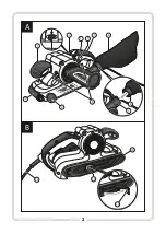
The sander is equipped with external sockets for graphite brushes (
8
)
Wood must always be ground in the direction of its growth rings - sanding
allowing for easy replacement of brushes with the help of a wide flat
across the growth rings can bring undesirable results.
screwdriver, and without the need for dismantling its case. After
An abrasive belt used for sanding metals should not be used for other
replacement, the brush fastening caps must be firmly tightened. Condition
materials.
of the brushes must be inspected at regular intervals. Minimal length of the
NOTE:
Only abrasive belts in technically intact condition guarantee good
graphite part of a brush is 6 mm. Operation with brushes shorter than 6 mm
performance of processing and prevent damage to the power tool.
can cause damage to the commutator of the rotor.
n
Brushes must be replaced in pairs. After replacement the sander must be run
idle for 5 minutes.
NOTE:
Before fitting and removal of the belt, make sure the sander is powered
OFF and disconnected from the power supply.
Should you encounter any technical problems, please contact an authorized
service centre.
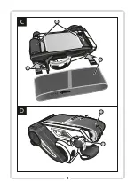
1. Pull the belt tensioning lever (
11
) to the outside to unlock the abrasive
belt (
10
) (see: fig.
B
, page 2).
TRANSPORT:
2. Pull the used-up abrasive belt off the guiding rollers (
13
).
The sander must be transported and stored in its original transport case
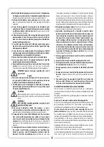
3. Pull a new abrasive belt (
10
) over the guiding rollers (
13
), paying
which protects it from mechanical damage.
attention to the direction of rotation of the abrasive belt (arrows on the
inner side of the abrasive belt) to correspond with the direction of
rotation of the sander (an arrow over the rear guiding roller) (see: fig.
C
,
page 3).
4. Pull the belt tensioning lever (
11
) backwards, to tension the new
abrasive belt.
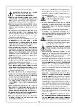
Adjustment of the belt track
D
Power the sander ON at low speed and check whether the abrasive belt (
10
)
is positioned properly. If the edge of the belt sticks behind or does not reach
the base edge by more than 6 mm, use the belt position adjustment knob
(
9
) to adjust the belt track.
STORAGE AND MAINTENANCE:
The sander requires virtually no special maintenance. The sander must be
stored in a place unavailable to children, in a clean condition and protected
from humidity and dust. Storage conditions should prevent the possibility
of mechanical damage and the influence of weather conditions.
Cleaning
In order to provide safe and efficient operation, case and ventilation gaps of
the sander should always be free of dust and fouling, if only possible. It is
recommended to clean the tool immediately after each use.
Wipe off the sander with a soft, damp rug with a minute amount of soap.
Do not use any cleaning agents or solvents; they can damage plastic parts of
the sander.
Take care to not let water inside the device.
- check whether the power cord (
12
) is correctly plugged in and the
electric power outlet is energized;
- check condition of carbon brushes and replace them if necessary.
Replacement of the abrasive belt
ENVIRONMENTAL PROTECTION
:
NOTE
:
The symbol nearby denotes that old equipment must
never be disposed together with other wastes (with the penalty
of a fine). Hazardous components of electronic equipment may
adversely affect the natural environment and human health.
Each household may contribute to recovery and reuse (recycling) of old
(see: fig. , page 3)
machinery and equipment. Both in Poland and Europe a system for recovery
of used equipment either exists or is being developed. The system obliges all
organizations that sell such equipment to collect back the used machinery
and appliances. Moreover, general purpose collecting points for such
equipment are also available
MANUFACTURER:
PROFIX
Co.
Ltd.,
34
,
Marywilska
St., 03-228 Warsaw, POLAND
This device meets the requirements of national and European standards and
safety guidelines.
NOTE!
Any repair can be carried out only by qualified
personnel using original spare parts.
n
PICTOGRAMS:
NOTE!
Prior to commence any maintenance or repair jobs make
Explanation of the icons located on the nominal plate and the information
sure that the device is disconnected from the electric power
tags
:
network.
After using the tool it is recommended to clean the ventilation openings
with compressed air to avoid damage to the bearings and remove dust
blocking the air used for cooling the motor.
TROUBLESHOOTING:
The electric tool fails to switch on or works with breaks:
n
7
«Always wear safety goggles»
«Read this instruction before switching on the
power supply and starting the work»
«Wear hearing protection»
«Wear a dust mask»
The policy of the PROFIX company consists in permanent improvements of the offered products and therefore the company
reserves the right to make amendments to the product specification without a prior notice. The images included into the
operation manual are only of the exemplary nature and may slightly differ from actual appearance of the device purchased.
This
instruction
manual
is
protected by copyright.
Copying it
without the written consent of PROFIX Co. Ltd. is prohibited.
Summary of Contents for TMT810
Page 2: ...2 B A 11 5 6 7 1 2 3 4 5 6 810W 9 10 12 11 6 5 8 10...
Page 3: ...3 D C 13 P 1 2 0 10 11 10 9...
Page 13: ...13 TMT810 TMT810K RCD 30 RCD...
Page 14: ...14 a a PROFIX...
Page 15: ...15 2 a 10 6...
Page 17: ...17 4 4 11 3 3 n 4 D 3 n 10 2 6 9 n n n n 8 1 11 10 B 2 2 13 6 6 3 10 13 5 C 3 810K 12...
Page 18: ...PROFIX 18 n 03 228 34...
Page 44: ...www profix com pl...