


© Trynex International 2009 L1188
GR4 — 11
Assembly Instructions
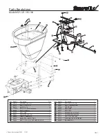
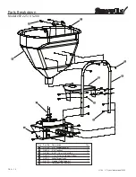
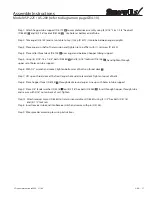
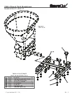
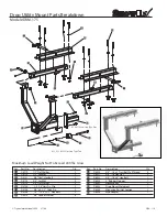
Model #SP-225 / US-200 (refer to diagram on page GR4-10)
Step 1:
Attach hopper tube support (D 6712) to complete drive assembly using (4) 5/16"-18 x 1-3/4" hex bolt
(D6462) and (4) 5/16” locknut (D6138) . Use holes at bottom end of tube.
Step 2:
Take auger (D 6122) and set on table to tap (1) cap (D 6191) into tube between auger uprights.
Step 3:
Place auger on shaft of transmission and tighten to top of flat with (1) set screw (D 6140).
Step 4:
Place salter throat deck (D 6702) over auger and between hopper tubing support.
Step 5:
Using (4) 5/16"-18 x 1-3/4" bolts (D 6462) and (4) 5/16" locknuts (D 6138) , hand tighten through
upper set of holes on tube support.
Step 6:
With 1/2" wrench and socket, tighten bottom set of bolts on throat deck
.
Step 7:
Lift up on throat deck at the front (auger hole side) to level deck. Tighten top set of bolts.
Step 8:
Place hopper throat (D 6754) through deck around auger. Line up with holes in tube support.
Step 9:
Place 3/8" fender washer (D 4318) on (4) 5/16" hex bolts (D 6462) . Insert through hopper, through tube
and secure with 5/16" nut on back of unit. Tighten.
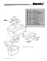
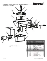
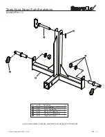
Step 14:
Attach receiver mount (D 6485) to transmission weldment (D 6480) using (4) 1/2" hex bolts (D 4116)
and (4) 1/2” lock nuts.
Step 8:
Insert receiver tube end into Receiver Hitch and secure with pin (D 4136).
Step 9:
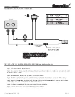
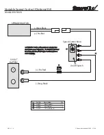
Wire spreader according to wiring instructions.


