16
Tool assembly
E464EN_04.DOC
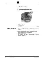
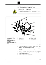
1. Push the turning handle when the machine is either running or
switched off and rotate it.
2. The turning handle locks into place when it is released.
3. Marker points have been placed on the turning handle (27)
which are to be positioned in accordance with sheet thickness
and the particular application to be carried out.
4. Altering the clearance between the two blades allows
optimisation of cutting behaviour to match particular
applications.
Note
3
(+)
intermediate stage in direction of rotation 2
(-)
intermediate stage in direction of rotation 1
Sheet thickness
[mm]
Setting of the
turning handle
for the cutting of
curves
Setting of the
turning handle
for the cutting of
straight lines
Setting of the
turning handle
for the cutting of
coils
3.5 3(+) 3(+) -
3.0 3(+) 3 1
2.5 3 2(+) 1
2.0 2(+) 2 1
1.5 2 1(+) 1
1.0 1(+) 1 1
0.5 1 1(-) 1(-)
3
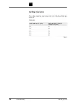
The settings listed in the Table are recommended values.
Changing the height
clearance between moving
cutter blade and fixed
cutter blade
Table 5


