10
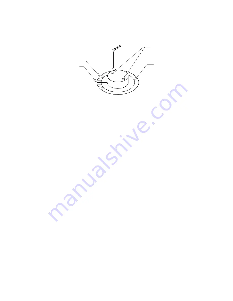
1/16th Hex Screws
Ring Scale
Zero Mark
Dial Ring
Figure 7
Calibration of the TLT-44
To calibrate TLT-44 it must be assembled. Figure 20 shows the bar placed under the front
wheels of the vehicle to be measured. Since the bar rests near the front wheels, it is tilted
the same amount as the vehicle. The compensation procedure that follows corrects for the
tilt. After assembly, the bar is calibrated according to the following procedure on the
following page.
Summary of Contents for TLT Series
Page 28: ...28 Two Wheel Centerline Alignment Figure 22...
Page 31: ...31 Tracking...


