background image


21 / 53 

8018_SP1500 

V2.2_EN (03/2018)


5.3   Secondary Risks 


3.1 General 


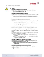
Hazard due to materials hazardous to health! 


In processing with or use (cleaning, etc.) of hazardous materials 
(toxic, etc.), appropriate measures should be taken to avoid health 
hazards.


Hazard due to operator error! 

Errors are possible even when the machine is operated properly following the 
functions and sequences described in the operating manual. Such errors may 
lead to death, bodily injury and/or damage to the machine. 


Do not initiate any work or adjustment activities while any 
personnel are located in the hazardous area.


Hazard due to add -on options or machines! 

Adding on options or machines can lead to unknown risks and hazards. 


Modifications made to the machine without approval by Trotec 
invalidates the Conformity Declaration (CE) supplied with the 
product. 


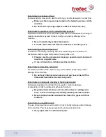
3.2 Crushing hazard 


Hazard due to moving parts! 

Reaching, stepping or leaning into the hazardous area may result in serious 
injury by crushing body parts, severing fingers or the hand! 


Do not initiate any work process on the machine while persons 
(helpers, etc.) are located in the hazardous area of the machine. 


Prohibit access to the hazardous area. 


Wear suitable work clothing (no loose clothing, jewellery, or 
similar.). 


Summary of Contents for SP1500

Page 1: ...SP1500 Operation Manual...

Page 2: ...parts of it without the approval of Trotec Laser GmbH is subject to prosecution We do not assume liability for any errors contained in this documentation We reserve the right to make technical changes...

Page 3: ...ling option 13 4 11 Materials 14 5 Safety 15 5 1 Safety Instructions 15 1 1 Intended user group 15 1 2 Operating instructions Safety equipment 15 5 2 General Safety Instructions 16 2 1 General 16 2 2...

Page 4: ...37 8 5 Operation 38 8 6 Changing the lens 39 9 Maintenance 44 9 1 Cleaning optics on the Laser Head 44 9 2 Cleaning the Mirrors 45 9 3 Cleaning the Exhaust hose connector 46 9 4 Maintenance plan 47 10...

Page 5: ...manufacturing label with the CE sign on the back side of the machine Enter the serial number model and year of manufacture from the manufacturing label here This information is important for troublesh...

Page 6: ...6 53 8018_SP1500 V2 2_EN 03 2018 2 Product Components Lenses 2 5 5 7 5 optional RS232 cable TroCAM i Cut 7 5 optional...

Page 7: ...nd Utilizing the machine s capabilities according to its intended use The operating manual contains important notes on how to operate the machine Safely Properly and Economically Following the operati...

Page 8: ...or instructions Any accidents that occur Other unusual observations Recommendations for improvement requests This information serves as a basis for potential corrections and or changes to the product...

Page 9: ...trols for the SP1500 are located on the keypad The SP1500 is equipped with an interlock safety system When the interlock is activated only setup tasks can be performed on the SP1500 The machine has a...

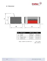
Page 10: ...018 4 3 Dimensions Weight depends on product model 1200 1300kg 2646 2867 lbs Item Description Dimension Units A Length 2829 112 mm inch B Width 2197 87 mm inch C Height closed 1293 51 mm inch D Height...

Page 11: ...g system Lenses 2 5 and 5 0 Standard 7 5 optional Lenses and all reflective mirrors are air flushed and therefore protected from soiling preinstalled air pump Max area load of workpiece table 25 kg 55...

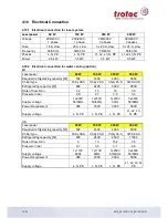
Page 12: ...respectively process gas Considered for control of compressed air and process gas free of mechanical dust water and oil max flow rate 150 l min 40 gpm with max 10 bar 145 psi max limit 4 bar on worki...

Page 13: ...8000 Chiller type Chilly 08 S Chilly 25 S Chilly 45 S CWK 90 S Refrigerating capacity W 890 2400 5300 9500 Rate of flow l min 7 2 10 16 30 Pressure in bar 2 9 2 7 3 5 3 4 Supply voltage 1x230V 50 60H...

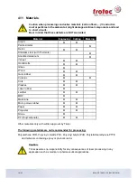
Page 14: ...ed aluminum Veneer Handicrafts Glass Wood Gum rubber Ceramic Cork Plastics Laser rubber Leather MDF Melamine Micro porous rubber Paper Polyester Stone PC Polycarbonate Other materials only with writte...

Page 15: ...only be operated by authorized persons Authorities must be clearly defined and observed so that no unclear competencies result under the aspect of safety This applies in particular to work performed o...

Page 16: ...or lighting poor housekeeping and moisture Shadows reflections and poor housekeeping increase the risk of an accident Light the work area well and always keep it clean and dry Hazard due to missing de...

Page 17: ...machine movements for proper operation and check work results on a regular basis In case of deviations initiate prescribed actions Hazard due to premature actuation Premature actuation of the machine...

Page 18: ...ispose of waste in accordance with applicable legal regulations Hazard due to inferior replacement parts or parts from other companies The use of inferior replacement parts or parts from other compani...

Page 19: ...interlock system Hazard in processing unapproved material Processing of materials not listed and approved in this operating manual is prohibited Processing medical technology and pharmaceutical produc...

Page 20: ...ting loads Avoid unnecessarily long periods of lifting Do not lift loads until you have a clear view of the travel route Choose travel routes that are as unobstructed as possible Hazard due to lifting...

Page 21: ...ent activities while any personnel are located in the hazardous area Hazard due to add on options or machines Adding on options or machines can lead to unknown risks and hazards Modifications made to...

Page 22: ...7 External next to the power socket 8 a External service panel front locker b External service panel back locker c Internal service panel cover of electronics 9 External at the front cover right side...

Page 23: ...3 53 8018_SP1500 V2 2_EN 03 2018 Front and right side Back and left side 8 9 2 5 10 1 3 1 8 11 1 3 10 4 10 2 6 10 position depends on laser type 4 10 position depends on laser type 1 3 10 8 11 7 11 1...

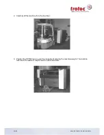
Page 24: ...housing is reinforced only on certain positions so that a fork lift truck can lift the machine The following suspension points are available machine front and back left and right side These positions...

Page 25: ...P1500 V2 2_EN 03 2018 2 Carefully lift the machine from the box floor 3 Position the SP1500 on an even floor capable of carrying the machine weight This location must meet the ambient requirements men...

Page 26: ...ipping packaging Dispose of packaging according to applicable waste disposal law Inspect machine and machine parts for shipping damage Check shipment for completeness In case of shipping damage or inc...

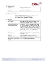
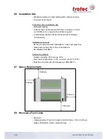
Page 27: ...least 500 kg m2 105 lbs sq ft Installation site must Be free of noisy electrical installations hoses and pipe lines Have power supply that is free of fluctuations Be shielded from EMC Ambient Conditi...

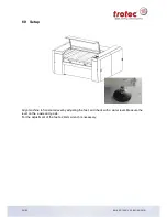
Page 28: ...00 V2 2_EN 03 2018 6 9 Setup Align machine to horizontal level by adjusting the feet and check with a water level Measure the level on the x axis and y axis For the adjustment of the feet a 24mm wrenc...

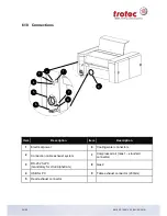
Page 29: ...escription 1 Electrical power 6 Cooling water connectors 2 Connection cable exhaust system 7 Compressed air Gas 1 standard connector 3 RS 232 for PC mandatory for i Cut AlphaCam 8 Gas 2 4 USB for PC 9...

Page 30: ...connect the water in of the SP1500 with the water out of the chiller and the water out of the SP1500 with the water in of the chiller 1 Start the chiller 2 Start the laser machine note order Sketch o...

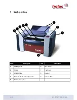
Page 31: ...EN 03 2018 7 Machine view Item Description Item Description 1 Working head 6 Main switch 2 X Axis 7 Top Cover 3 Working table 8 Keypad 4 Removal door for leavings waste 9 Service Panel 5 Maintenance p...

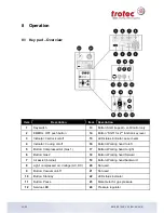
Page 32: ...status indicator Laser beam 4 Indicator Cooling on off 16 Button Working head to left 5 Button Compressed Air Gas 1 17 Button Working head to right 6 Button Gas 2 18 Button Working head forward 7 Air...

Page 33: ...nlit the machine is ready for production Cooling on off indicator 4 Switching in process gas Compressed Air Gas 1 on off key 5 Gas 2 on off key 6 Pressure regulator 24 This is used to adjust the requi...

Page 34: ...ocess being executed is stopped Lamp for service plug 12 Lights when a service plug is inserted Technician Start Repeat key 13 Key for starting the job program and repeating the last job program see p...

Page 35: ...ight 17 Key Working head forward 18 Key Working head backward 19 When 2 adjacent keys are pressed simultaneously e g keys 16 and 19 the laser head moves diagonally Movements of the work table 20 21 No...

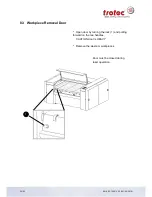
Page 36: ...00 V2 2_EN 03 2018 8 3 Workpiece Removal Door Open door by turning the lock 1 and pulling forward on the two handles CAUTION door is HEAVY Remove the waste or workpieces Door must be closed during las...

Page 37: ...Vacuum Table The vacuum table is only intended for engraving and or cutting thin and lightweight materials such as films plastic laminates veneers thin sheets of wood paper cardboard and similar The e...

Page 38: ...l reference movement is finished covers have to be closed Drive the laser head to its forward end position and drive it upward with the adjusting screw 4 Clean lens reinstall and secure Install nozzle...

Page 39: ...void direct contact with the optics Overview 1 Turn the laserhead all the way down to allow enough space 2 If necessary reduce the distance from the nozzle to the material to move even further down 2...

Page 40: ...V2 2_EN 03 2018 3 Loosen the two screws to remove the cylinder 4 Loosen the cylinder by turning 5 Remove both cylinders together from the laser head outer and inner cylinder see overview 6 Lay the out...

Page 41: ...emove the lens 8 Put the lens on a cleaning cloth Clean the lens on both sides with the cleaning fluid and wipes Check lens for cleanliness and damage 9 Put the lens correctly in the socket Put the cu...

Page 42: ...he cylinder back into the laserhead and screw it in If both cylinders are not concentrically fixed over the thread the lower cylinder cannot be screwed into the thread 12 Tighten the two previously lo...

Page 43: ...3 8018_SP1500 V2 2_EN 03 2018 13 Screw the laserhead back in the Z direction 14 Focus with the corresponding focus tool and adjust the distance to the nozzle to the material surface approx 1 cm by def...

Page 44: ...ain Reinstall mirror holder 3 and secure with two screws 2 Cleaning lenses Loosen the two screws 4 holding the upper cylinder 5 Loosen the lower cylinder 6 by screwing it inward Remove both cylinders...

Page 45: ...o 10 6 Remove cover 1 by pulling on the handles 7 3 mirrors 2 must be cleaned Loosen both screws 3 Remove mirror holder 4 Check mirror 5 for damage Clean mirror 5 with Cleaning fluid and cleaning clot...

Page 46: ...k the protective grid weekly and optionally remove the deposits and clean the grid to ensure a good extraction Risk of fire by depostis Deposits in the exhaust hose connections may occur flame formati...

Page 47: ...ective grid Check Cleaning if required Entire working area general cleaning Cleaning Exhaust System Bag filter According to the operation manual of the exhaust system Filter mat Particle filter Activa...

Page 48: ...t essential health and safety requirements of the EC machinery directive 2006 42 EEC Further valid guidelines regulations for the product 2006 95 EG Low Voltage Directive 2004 108 EG EMC Guideline App...

Page 49: ...eration of the machine discussed Maintenance of the machine discussed Electrical voltage checked Safety Instructions discussed Trial run performed Deficiencies determined The machine with the Please t...

Page 50: ...covered Machine Function Danger Area Warnings Position Emergency OFF Button Personal Protective Equipment Operating Facilities Work Flow Setting up Taking into Service and Shutdown Announcement of une...

Page 51: ...etails Contact Details Serialnumber Name JobControl Version Country Driver Version Phone Number Layout Software Email address Firmware Version Problem Description Does an Error message show up on the...

Page 52: ...1 Start JobControl 2 Position the job which possibly caused a failure on the plate 3 Run the job and leave the job on the plate 4 Go to Settings Create Service File 5 The window Save Service File to s...

Page 53: ...and possibly caused a failure example Corel file Photoshop file AutoCAD file Click on Open 7 The following window confirms that the Service File ServiceLog txt was created successfully 8 Please send t...

Reviews: