background image


Operating manual – Infrared camera


B -


18

  warnInG: do not at any time change the file  

  name to one that you have thought up yourself.  

  this could lead to the memory card not being  

  able  to  identify  the  file  and  stop  the  memory  

  from booting successfully.

08. cOnnectIOn and dOwnlOad

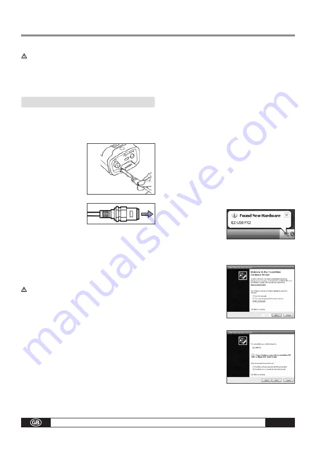
Connecting to a monitor 

A  video-compatible  monitor  connected  via  the  sup-
plied video cable can be used to view and analyze the 

images you shoot.
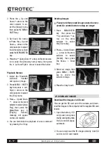
1.  Turn off the IR camera.
2. Attach the video cable  
    to  the  video  out  
    terminal on the multi- 
    functional dock.
3. Plug the other end of  
    the video cable to the  
    video  in  jack  on  the  
    monitor.
4. Turn on the monitor and the IR camera. 
5.  If necessary please switch the video format in the setup  
    menu of the camera from PAL into NTSC or reversed.

Connecting to a computer (only for Real-Time)

Insert the software-CD into your computer. The instal-
lation routine starts automatically.

Actually USB real time monitor only supports 

Windows XP operation system. You only can 

connect one USB camera at one time.

First connect the dongle to a USB-port of your compu-
ter. Without that dongle the software can not be ope-
ned. Then Go to „Monitor“ and choose the IR-camera 
model  that  should  be  connected  to  the  computer.  In 
case of an EC-camera you do not need to turn off the 
computer or camera when making this connection. The 
EC-cameras can be connected via the multifinctional 
docking-station. In case of any problems, please refer 
to your computer manual or your administrator for more 
information regarding the location of the USB port. The 
USB-Port of the camera can only be used in combinati-
on with the optional USB Real-Time software.

If  using  an  IC-/Hotfind-camera  please  follow  this 
chronological order:
Connect one end of the USB cable to your PC.
Power up the camera and wait several seconds until 
the vertical colour bars appear on the LCD.
Connect the other end of your USB cable to the USB 
port of your infrared camera while the colour bars are 
still on the display.
As soon as the camera has been identified you will be 
automatically requested to install the drivers. Proceed 
as described in the following passages

Installing the driver (Only for Real-Time Software/ 

optional)

Users of Windows XP Professional must first log in as 
Administrators  (computer  system  administrators)  to 
install programs.

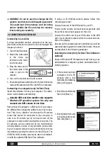
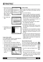
1.  If the camera has been  
    connected  to  the  PC  
    properly  after  a  few  
    moments, the following 
    dialog will appear.

2. Select [No, not this time] 
    then click [Next >].

3. Select [Install from a list  
    or location (Advanced)]  
    then click [Next >].

Summary of Contents for IC 0120 LV

Page 1: ...GmbH Co KG Grebbener Stra e 7 D 52525 Heinsberg Tel 49 0 24 52 962 400 Fax 49 0 24 52 962 200 www trotec de E Mail info trotec de TRO TR BA LV V SERIE 01 10 GB LV V Serie Operating manual Infrared cam...

Page 2: ...lte B 15 Opening Images B 15 Playback Memos B 15 Deleting Images B 16 07 Download the Images B 17 Download via SD Card B 17 08 Connecting and Download B 18 Charging via the Dock B 18 Connecting to a M...

Page 3: ...l shock Immediately turn the IR camera s power off remove the IR camera battery or unplug the power cord from the power outlet Ensure that smoke and fume emissions have ceased Stop operating immediate...

Page 4: ...harging and when the IR camera is not in use to avoid fires and other hazards Continuoususeoveralongperiod of time may cause the unit to overheat and distort resulting in fire Do not use the battery c...

Page 5: ...tifunction dock port Illuminator Visual lens IR lens Laser Pointer Definable trigger Battery pack cover Lens locker Key pad LCD display Cancel Power indicator Auto adjust Menu Enter Freeze Saving Powe...

Page 6: ...re is no need to complete use or discharge it before recharging It can be recharged at any time However since the maximum number of charge cycles is approximately 300 battery life it is recommended to...

Page 7: ...shooting image The display shows the Info view About the operation indicator The operation indicator shows the status of the camera Menu Represents the menu mode Null Represents the non menu mode no a...

Page 8: ...he built in menu system 1 Check that the IR camera is in null mode 2 PresstheMENU ENTER key then press the Up or Down ar row on the omni selector to select the Setup menu 3 Press the Up or Down arrow...

Page 9: ...the subject in cen ter of the image that is shown on the LCD monitor The LCD will shut off when closed Selecting Menus and Settings You can select the settings by pressing the MENU KEY key 1 Press th...

Page 10: ...t the IR camera is in null mode 2 Aim the IR camera at the subject 3 Turn the focus ring to focus on the target 4 Do not stop turning until the image is clear Thermal Visual and Duovision image displa...

Page 11: ...en press the directional keys to have the CCD super posed on the IR image WARNING This setting depends on the distance and only possible in the scope of certain opera tions for technical reasons Image...

Page 12: ...The ca mera provides 6 palettes Iron Iron inverted Rainbow Feather Grey and Grey inverted Auto adjust Sets the function of the A key There are three options Level and Span Level Span Level und Span Th...

Page 13: ...range Press the 3 Left or Right 4 ar row on the omni se lector to select a range Press the Up or Down arrowonthe omni selector to set measurement range This option is unavailable when the image is fr...

Page 14: ...nges or press the C key to close the menu window without saving About the analysis settings Capture Spot max min spot Sets spot 4 to automatically track the highest lowest spot on the screen Maximum S...

Page 15: ...omatically Isotherm analysis Select this camera function to Isothermal Analysis Mode for the IR image in question The measuring object within a specific temperature range is then displayed in the same...

Page 16: ...TER key 2 Press the 3 Left 4 Right arrow on the omni selector to select the File me nu 3 Press Up and Down arrow on the omni selector to select Save then press the Menu Enter key to save the image The...

Page 17: ...sing the trigger Lightingon Youcanactivte deactivatetheilluminatorby pressing the trigger 06 Playback and Delete Opening Images You can view and analyze the recorded images on the LCD monitor 1 Press...

Page 18: ...ying Record message will appear on the LCD monitor 4 You can terminate the playback of voice comment by pressing the C key Deleting Images Please note that erased images cannot be reco vered Be carefu...

Page 19: ...ra model that should be connected to the computer In case of an EC camera you do not need to turn off the computer or camera when making this connection The EC cameras can be connected via the multifi...

Page 20: ...wsMe Windows 2000 or Windows XP VISTA preinstalled The USB interface is not supported by systems not complying with the conditions above 2 Is the camera correctly connected to the computer See Connect...

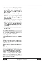
Page 21: ...nnection to the Blue tooth headset 6 The headset allows you to record voice memos or play back memos 09 Care and Maintenance Use the following procedures to clean the camera body lens LCD monitor and...

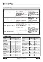
Page 22: ...ed quickly Battery pack capacity reduced because of disuse for one year or more after being fully charged Replace the battery pack with a new one Battery life exceeded Replace the battery pack Battery...

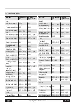
Page 23: ...1400 0 29 Melting mild steel 1600 1800 0 28 Liquid steel 1500 1650 0 42 0 53 Pure lead 1515 1680 0 42 0 45 Silver Polished Silver 100 0 05 Material Temperature C Emissivity approximation Nickel Nickel...

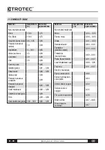
Page 24: ...95 Solid materials 0 80 0 93 Ceramics vase type 0 90 Film 0 90 0 93 Heat resistance glass 200 540 0 85 0 95 Material Temperature C Emissivity approximation Non metal materials Mica 0 94 0 95 Flume mic...

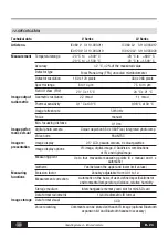
Page 25: ...point Isotherm Image re presentation Colour depiction 680 x 480 Pixel integrated photo lamp PAL NTSC 2 5 LCD pseudo colours 6 colour palettes IR image digital image 4 DuoVision combinations of IR and...

Page 26: ...rd lens Standard equipment USB 2 0 Composite Video 20 x 15 24 x 21 Camera with standard lens LCD display and laser battery charger 110 230 Volt IC090 Ex protected with charging status indicator Li ion...

Page 27: ...Operating manual Infrared camera B 26...

Page 28: ......

Page 29: ......

Page 30: ...TROTEC GmbH Co KG Grebbener Stra e 7 D 52525 Heinsberg Tel 49 0 24 52 962 400 Fax 49 0 24 52 962 200 www trotec de E Mail info trotec de...

Reviews: