5
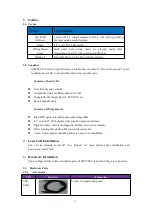
Port No.
Title
Explanation
1
24V
24V positive polarity
2
GND
24V grounding
3.2.2.2. Port of Panel and Wiring Board
CN cables connecting panel to wiring board.
Title
Explanation
CN1
Connect CN1 to panel
CN2
Connect CN2 to panel
3.2.2.3.
Signal Input Port on Wiring Board
There are two ports for signal input.
Ports
No.
Title
Explanation
11.IN 1
DC24V 24V Power supply positive polarity output
2
IN1
Open cover protection signal is effective to low logic level
3
IN2
Foot switch signal is effective to low logic level
4
IN3
Reserved
5
IN4
Reserved
6
GND
Grounding output
12.IN 1
DC24V 24V Power supply positive polarity output
2
IN5
Reserved
3
IN6
Reserved
4
GND
Grounding output
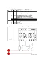
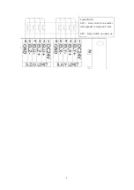
Wiring diagram for signal input:


