background image

3PC

1-1-1

1-1 Specifications

1-1-1  Specifications

NOTE: These specifications are subject to change without notice.

Item

Specifications

Paper weight

60 to 256g/m

2

Paper types

Plain (80g/m

2

 or less), Thick (256g/m

2

 or less), recycled

Paper size

A4, B5,Letter

Paper capacity

3000 sheets (1,500 sheets x 2) (80g/m

2

)

Dimensions

590 (W) x 626.9 (D) x 332 (H) mm
23 

1/4

” (W) x 24 11

/16

” (H) x 13 

1/16”

 (D)

Weight

Approx. 29kg / Approx. 63.9 lbs

Power source

Electrically connected to the machine. (3.3 V DC, 24 V DC)

Summary of Contents for Utax PF 810

Page 1: ...Service Manual Paper Feeder PF 810 Rev 2 0 Date 28 07 2014 3PCSM062 ...

Page 2: ...Service Manual Paper Feeder PF 810 Rev 2 0 Date 28 07 2014 3PCSM062 ...

Page 3: ...ficials for details in your area for proper disposal ATTENTION IL Y A UN RISQUE D EXPLOSION SI LA BATTERIE EST REMPLACEE PAR UN MODELE DE TYPE INCORRECT METTRE AU REBUT LES BATTERIES UTILISEES SELON LES INSTRUCTIONS DONNEES Il peut être illégal de jeter les batteries dans des eaux d égout municipales Vérifiez avec les fonctionnaires municipaux de votre région pour les détails concernant des déchet...

Page 4: ...Revision history Revision Date Replaced pages Remarks 1 15 May 2014 1 2 3 Address 2 14 July 2014 1 4 4 ...

Page 5: ...This page is intentionally left blank ...

Page 6: ...rsonnel to ensure the safety of their customers their machines as well as themselves during maintenance activities Service personnel are advised to read this booklet carefully to familiarize themselves with the warnings and precautions described here before engaging in maintenance activities ...

Page 7: ... this symbol CAUTION Bodily injury or damage to property may result from insufficient attention to or incorrect com pliance with warning messages using this symbol Symbols The triangle symbol indicates a warning including danger and caution The specific point of attention is shown inside the symbol General warning Warning of risk of electric shock Warning of high temperature indicates a prohibited...

Page 8: ...d or dusty place This may cause fire or electric shock Do not install the copier near a radiator heater other heat source or near flammable material This may cause fire Allow sufficient space around the copier to allow the ventilation grills to keep the machine as cool as possible Insufficient ventilation may cause heat buildup and poor copying performance Always handle the machine by the correct ...

Page 9: ... carefully Always check that the copier is correctly connected to an outlet with a ground connection Check that the power cable covering is free of damage Check that the power plug is dust free If it is dirty clean it to remove the risk of fire or electric shock Never attempt to disassemble the optical unit in machines using lasers Leaking laser light may damage eyesight Handle the charger section...

Page 10: ... caution labels that should be present on the machine according to the instruction handbook are clean and not peeling Replace with new ones if necessary Handle greases and solvents with care by following the instructions below Use only a small amount of solvent at a time being careful not to spill Wipe spills off completely Ventilate the room well while using grease or solvents Allow applied solve...

Page 11: ...This page is intentionally left blank ...

Page 12: ... 1 4 1 2 Paper mis feed detection condition 1 4 1 1 4 2 Self diagnostic function 1 4 3 1 Self diagnostic function 1 4 3 2 Self diagnostic codes 1 4 3 1 4 3 Electric problems 1 4 6 1 4 4 Mechanical problems 1 4 8 1 5 Assembly and Disassembly 1 5 1 Precautions for assembly and disassembly 1 5 1 1 Precautions 1 5 1 1 5 2 Paper feed section 1 5 2 1 Detaching and refitting the PF forwarding PF paper fe...

Page 13: ...er feed 2 1 3 4 Left cassette paper feed 2 1 5 2 2 Electrical Parts Layout 2 2 1 Electrical parts layout 2 2 1 1 PWB and sensors 2 2 1 2 Motors and others 2 2 3 2 3 Operation of the PWBs 2 3 1 PF main PWB 2 3 1 2 4 Appendixes 2 4 1 Appendixes 2 4 1 1 List of maintenance parts 2 4 1 2 Periodic maintenance procedures 2 4 2 3 Wiring diagram 2 4 3 ...

Page 14: ...er weight 60 to 256g m2 Paper types Plain 80g m2 or less Thick 256g m2 or less recycled Paper size A4 B5 Letter Paper capacity 3000 sheets 1 500 sheets x 2 80g m2 Dimensions 590 W x 626 9 D x 332 H mm 23 1 4 W x 24 11 16 H x 13 1 16 D Weight Approx 29kg Approx 63 9 lbs Power source Electrically connected to the machine 3 3 V DC 24 V DC ...

Page 15: ...3PC 1 1 2 1 1 2 Parts names Figure 1 1 1 1 2 3 4 1 Cassette 4 2 Cassette 3 3 Lift plate 4 PF paper conveying cover ...

Page 16: ...3PC 1 1 3 1 1 3 Machine cross section Figure 1 1 2 Paper path ...

Page 17: ...3PC 1 1 4 This page is intentionally left blank ...

Page 18: ...humidity or low temperature and low humidity an abrupt change in the environmental temperature and cool or hot direct air Avoid places subject to dust and vibrations Choose a surface capable of supporting the weight of the machine Place the machine on a level surface maximum allowance inclination 1 Avoid air borne substances that may adversely affect the machine or degrade the photo conductor such...

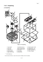
Page 19: ...3PC 1 2 2 1 2 2 Unpacking 1 Precaution for unpacking Hold the positions shown in the figure and remove the paper feeder from the outer case Figure 1 2 1 ...

Page 20: ... 1 5 2 3 9 11 7 6 8 12 16 17 10 14 15 13 14 1 Paper feeder 2 Outer case 3 Inner case 4 Bottom left pad 5 Bottom right pad 6 Upper left front pad 7 Upper left back pad 8 Upper right front pad 9 Upper right back pad 10 Top spacer 11 Rear spacer 12 Plastic sheet 13 Plastic bag 240 350 14 Plastic bag 70 110 15 Installation guide etc 16 Plate screws M3 8 17 Paper size plates ...

Page 21: ...3PC 1 2 4 2 Remove the tapes and pad Procedure 1 Remove eight tapes Figure 1 2 3 2 Remove six tapes and then remove the retainer and the leaflet Figure 1 2 4 Tapes Tapes Tapes Tapes Retainer Leaflet ...

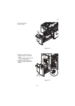
Page 22: ... plate stopper from cassette and attach it to the storage location When moving the machine attach the lift plate in original position 6 Gently push right cassette back in 7 Remove the stopper similarly for left cassette Figure 1 2 6 Right cassette Tape Right cassette Lift plate stopper ...

Page 23: ...he right cassette forward 2 Remove four screws and then remove the right cassette Figure 1 2 7 3 Pull the left cassette forward 4 Remove four screws and then remove the left cassette Figure 1 2 8 Screw Screw Screw Screw Rijght cassette Screw Screw Screw Screw Left cassette ...

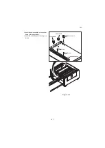
Page 24: ...C 1 2 7 5 Install three wire saddles on the bottom frame of the paper feeder 6 Install the cassette heater by using two screws Figure 1 2 9 Cassette heater Screw Screw Wire saddle Wire saddle Wire saddle ...

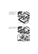
Page 25: ... 8 Pass through the wire of the cassette heater to three wire saddles Figure 1 2 10 9 Insert two hooks of the heater cover to the holes of base of paper feeder each 10 Install the heater cover by using a screw Figure 1 2 11 Cassette heater Connector Wire saddle Wire saddles Heater cover Screw Heater cover Hooks ...

Page 26: ...3PC 1 2 9 11 Adhere the high temperature caution label after wiping the bottom frame of this side of cassette heater with alcohol Figure 1 2 12 High temperature caution label ...

Page 27: ...3PC 1 2 10 This page is intentionally left blank ...

Page 28: ...meric keys Enter the maintenance item number using the cursor up down keys or numeric keys The selected maintenance item is run Press the stop key Press the start key Start End Maintenance mode is entered The maintenance item is selected Maintenance mode is exited Repeat the same maintenance item Run another maintenance item No No Yes Yes Enter 001 using the cursor up down keys or numeric keys and...

Page 29: ...ed and paper conveying system U034 Adjusting the print start timing LSU Out Top LSU Out Left 0 0 0 0 0 0 0 0 0 U051 Adjusting the deflection in the paper 0 0 0 0 Operation panel and support equipment U247 Setting the paper feed device Mode setting U327 Setting the cassette heater control Off U341 Specific paper feed location setting for printing function Off Off Off Other U901 Checking copy counts...

Page 30: ...to reenter the settings after initialization or replacement Method Outputs the report 1 Press the start key 2 Select the item to be output 3 Select Print 4 Press the start key A list is output When A4 Letter paper is available a report of this size is output If not specify the paper feed location The output status is displayed Display Output list Maintenance List of the current settings of the mai...

Page 31: ...slot 3 Turn the main power switch on 4 Enter the maintenance item 5 Press the start key 6 Select the item to be send 7 Press the start key Output will be sent to the USB memory Completion Press the stop key The screen for selecting a maintenance item No is displayed Item No Description Display Output list USB Text Sends output data to the USB memory text type USB HTML Sends output data to the USB ...

Page 32: ...rions 0501 01 08 01 01 4002 01 08 01 01 0501 01 08 01 01 4002 01 08 01 01 0501 01 08 01 01 4002 01 08 01 01 0501 01 08 01 01 4002 01 08 01 01 0501 01 08 01 01 4002 01 08 01 01 0501 01 08 01 01 4002 01 08 01 01 0501 01 08 01 01 4002 01 08 01 01 0501 01 08 01 01 4002 01 08 01 01 Service Call Log 8 7 6 5 4 3 2 1 Count 1881214 178944 5296 5295 2099 1054 809 30 Service Code 01 6000 01 2100 01 4000 01 6...

Page 33: ... type e Paper eject a Cause of paper jam Hexadecimal For details on the case of paper jam refer to Paper Misfeed Detection P 1 4 3 b Detail of paper source Hexadecimal 00 MP tray 01 Cassette 1 02 Cassette 2 03 Cassette 3 paper feeder 04 Cassette 4 paper feeder 05 to 09 Reserved c Detail of paper size Hexadecimal 00 Not specified 01 Monarch 02 Business 03 International DL 04 International C5 05 Exe...

Page 34: ...ccurrence of the previous diag nostics error is less than 8 all of the diagnostics errors are logged The total page count at the time of the self diagnostics error Self diagnostic error code See page 1 4 13 Example 01 6000 01 Self diagnostic error 6000 Self diagnostic error code number 10 Maintenance Log Count Item Remembers 1 to 8 of occurrence of replacement If the occurrence of the previous rep...

Page 35: ...sed of three log coun ters including paper jams self diagnostics errors and replacement of the toner con tainer f Paper jam g Self diagnostic error h Maintenance item replacing Indicates the log counter of paper jams depending on location Refer to Paper Jam Log All instances includ ing those are not occurred are dis played Indicates the log counter of self diag nostics errors depending on cause Se...

Page 36: ...nnected UG 34 Installed US English Scan extension kit A Not Installed FAX Information Slot1 Slot2 Rings Normal Rings FAX TEL Rings TAD Option DIMM Size 3 3 3 16 MB Print Coverage Average Total K 1 10 C 2 20 M 3 30 Y 4 40 Copy K 1 10 C 2 20 M 3 30 Y 4 40 Printer K 1 10 C 2 20 M 3 30 Y 4 40 FAX K 1 10 Period Last Page K C M Y Usage Page A4 Letter Conversion 1111111 11 2222222 22 3333333 33 4444444 4...

Page 37: ...000 0000000000000000 0000000000000000 0000000000000000 0000000000000000 000000000000 0000000000000000 0000000000000000 0000000000000000 0000000000000000 0000000000000000 0000000000000000 0000000000000000 0000000000000000 0000000000000000 0000000000000000 0000000000000000 0000000000000000 0000000000000000 0000000000000000 0000000000000000 000000000000 0000000000000000 0000000000000000 0000000000000...

Page 38: ...ence or absence of the IC card authentication kit Installed Not Installed Trial 16 Presence or absence of the internet fax kit Installed Not Installed 17 Presence or absence of the data security kit Installed Not Installed 18 Presence or absence of the UG 33 Installed Not Installed 19 Presence or absence of the UG 34 Installed Not Installed 20 Presence or absence of the USB keyboard Connected Not ...

Page 39: ... RP code Code the engine software version and the date of the previous update 39 RP code Code the main software version and the date of the previous update 40 NV RAM version _ 1F3 1225 _ 1F3 1225 a b c d e f a Consistency of the present software version and the database _ underscore OK Asterisk NG b Database version c The oldest time stamp of database version d Consistency of the present software ...

Page 40: ...eveloper unit Y Maintenance kit A Maintenance kit B Maintenance kit C 51 Panel lock information 0 Off 1 Partial lock 2 Full lock 52 USB information U00 Not installed U01 Full speed U02 Hi speed 53 Paper handling information 0 Paper source unit select 1 Paper source unit 54 Color printing double count mode 0 All single counts 1 A3 Single count Less than 420 mm length 2 Legal Single count 356 mm or ...

Page 41: ...rmation 70 Calibration information 71 Calibration information 72 Calibration information 73 Calibration information 74 75 76 77 Calibration information 78 Calibration information 79 RFID information 80 RFID reader writer version infor mation 81 Color table version for printer 82 Color table 2 version for printer 83 Color table version for copy 84 Color table 2 version for copy 85 Maintenance infor...

Page 42: ... low setting 0 Enabled 1 Disabled 93 Toner low detection level 0 to 100 94 A shift restriction setup an one sheet manuscript 0 Enabled Shift restrictions off 1 Disabled Shift restrictions on 95 Full page printing mode 0 Normal Mode at Time of Factory Shipments 1 Full Page Mode 96 Drum serial number Black Cyan Magenta Yellow Code conversion A B C D E F G H I J 0 1 2 3 4 5 6 7 8 9 ...

Page 43: ... 2 Change the screen using the cursor up down keys Item No Description Display Description Main Main firmware MMI Operation firmware Panel Main Operation firmware Panel Boot Operation booting Browser Browser firmware Engine Engine firmware Engine Boot Engine booting Scanner Scanner firmware Scanner Boot Scanner booting RFID RFID firmware IH CPU IH CPU firmware IH CPU Boot IH CPU booting Dictionary...

Page 44: ...Boot Paper feeder booting DF Document finisher firmware DF Boot Document finisher booting MT Mailbox firmware MT BOOT Mailbox booting Fax APL1 FAX APL1 Fax Boot1 FAX boot1 Fax IPL1 FAX IPL1 Fax APL2 FAX APL2 multi port Fax Boot2 FAX boot multi port Fax IPL2 FAX IPL2 multi port Mode1 Installed application name Mode2 Installed application name Mode3 Installed application name Mode4 Installed applica...

Page 45: ...justment LSU Out Top 1 Press the system menu key 2 Press the start key to output a test pattern 3 Press the system menu key 4 Select the item to be adjusted Large size 218 mm or more in width of paper Item No Description Display Description LSU Out Top Leading edge registration adjustment LSU Out Left Center line adjustment Display Description Setting range Initial setting Change in value per step...

Page 46: ...rn 3 Press the system menu key 4 Select the item to be adjusted Item No Description Correct image Output example 1 Output example 2 Leading edge registration 20 1 5 mm Display Description Setting range Initial setting Change in value per step MPT Paper feed from MP tray 128 to 127 0 0 1 mm Cassette1 Paper feed from cassette 1 128 to 127 0 0 1 mm Cassette2 Paper feed from cassette 2 128 to 127 0 0 ...

Page 47: ...ase the value For output example 2 decrease the value Figure 1 3 5 6 Press the start key The value is set Completion Press the stop key The screen for selecting a maintenance item No is displayed Item No Description Center line of printing within 0 5 mm Correct image Output example 1 Output example 2 ...

Page 48: ...Change the setting value using the keys or numeric keys For output example 1 increase the value For output example 2 decrease the value The greater the value the larger the deflection the smaller the value the smaller the deflec tion Figure 1 3 6 7 Press the start key The value is set Completion Press the stop key The indication for selecting a maintenance item No appears Item No Description Displ...

Page 49: ...electing a maintenance item No is displayed Item No Description Display Description 2PF Paper feeder Display Description Motor Off PF paper feed motor PFPFM is turned off On PF paper feed motor PFPFM is turned on Device C1 Clutch PF paper conveying clutch 1 PFPCCL1 is turned on C2 Clutch PF paper conveying clutch 2 PFPCCL2 is turned on V Feed Clutch PF paper feed clutch PFPFCL is turned on H Feed1...

Page 50: ... printer output Purpose To use a paper feed location only for printer output A paper feed location specified for printer output cannot be used for copy output Method 1 Press the start key 2 Select the paper feed location for the printer When an optional paper feed device is not installed the corresponding count is not dis played 3 Press the start key The setting is set Completion Press the stop ke...

Page 51: ...per feed device is not installed the corresponding count is not dis played Clearing 1 Select the counts to be cleared Cassette3 and Cassette4 cannot be cleared 2 Select the counts for all and press Clear 3 Press the start key The counter value is cleared Completion Press the stop key The screen for selecting a maintenance item No is displayed Item No Description Display Description MPT MP tray Cas...

Page 52: ...ing unit or paper conveying cover The positions and the corrective actions are displayed on the touch panel when a paper jam has occurred Figure 1 4 1 B Misfeed in the vertical conveying part C Misfeed in the cassette 3 or 4 Figure 1 4 2 2 Paper mis feed detection condition Figure 1 4 3 JAM Paper jam 02 04 1 Open right cover 1 and remove the paper 2 Open the fuser cover a and remove the paper 3 Re...

Page 53: ...4 Multiple sheets in cassette 4 PF feed sensor 2 PFFS2 does not turn off dur ing paper feed from cassette 4 Bulk paper feeder C 2603 PF feed sensor 1 non arrival jam PF conveying sensor 1 PFPCS1 does not turn on during paper feed from cassette 3 Bulk paper feeder C 2604 PF conveying sensor 1 PFPCS1 does not turn on during paper feed from cassette 4 Bulk paper feeder C 2613 PF feed sensor 1 stay ja...

Page 54: ...detected for 1s or more 5 times succes sively However the first 1 s after PF lift motor 1 is turned on is excluded from detection Paper feeder lift base elevating mechanism Check that the cassette base can be manipulated smoothly if not repair or replace PF Lift motor1 1 Check that the cassette base has been ascended 2 Check the drive gear can rotate or they are not unusually loaded and if necessa...

Page 55: ...g is disconnected shorted or grounded replace the wiring 5 Replace the PF Lift motor2 PF Lift sensor2 1 Check that the sensor is correctly positioned 2 Confirm that the wiring connector is firmly connected and if necessary connect the connector all the way in PF Lift sensor 2 and PF main PWB YC4 3 If the wiring is disconnected shorted or grounded replace the wiring 4 Replace the PF Lift sensor 2 P...

Page 56: ...eeder When the PF paper feed motor is driven error signal is detected continuously for 1 s Defective connec tor cable or poor contact in the con nector Reinsert the connector Also check for conti nuity within the connector cable If none replace the cable PF paper feed motor and PF main PWB YC16 Defective drive transmission sys tem Check if the rollers and gears rotate smoothly If not grease the bu...

Page 57: ...r poor con tact in the connector Reinsert the connector Also check for continuity within the connector cable If none replace the cable PF lift motor 1 2 and PF main PWB YC7 2 Defective drive trans mission system Check if the rollers and gears rotate smoothly If not grease the bushes and gears Check for broken gears and replace if any 3 Defective motor Replace the PF lift motor 1 or 2 4 Defective P...

Page 58: ...nector cable or poor con tact in the connector Reinsert the connector Also check for continuity within the connector cable If none replace the cable PF paper size length switch 1 and PF main PWB YC3 PF paper size width switch 1 and PF main PWB YC3 PF paper size length switch 2 and PF main PWB YC6 PF paper size width switch 2 and PF main PWB YC6 2 Defective switch Replace the PF paper size length s...

Page 59: ...d PF paper width guide in a cassette installed incorrectly Check the PF paper width guide visually and remedy or replace if necessary 3 Multiple sheets of paper are fed Check if the paper is excessively curled Change the paper Paper is loaded incorrectly Load the paper correctly Check if the PF separation pulley is worn Replace the PF separation pulley if it is worn see page 1 5 2 1 5 7 4 Paper ja...

Page 60: ... handling PWBs printed wiring boards do not touch parts with bare hands The PWBs are susceptible to static charge Do not touch any PWB containing ICs with bare hands or any object prone to static charge When replacing battery on a PWB dispose properly according to laws and regulations When removing the hook of the connector be sure to release the hook Take care not to get the cables caught To reas...

Page 61: ...ation pulleys Right Procedure 1 Open the PF paper conveying cover 2 Remove the strap and then remove the PF paper conveying cover Figure 1 5 1 3 Remove four screws and then remove the right cover Figure 1 5 2 PF paper conveying cover Strap PF paper conveying cover Screw Right cover Screw Screw Screw Screw ...

Page 62: ...3PC 1 5 3 4 Pull out the right cassette 5 Remove the connector Figure 1 5 3 Connector ...

Page 63: ...3PC 1 5 4 6 Remove each two fixed screws of the PF primary paper feed unit 7 Remove the PF primary paper feed unit Figure 1 5 4 Screws PF primary paper feed unit PF Primary paper feed unit ...

Page 64: ...lley Right 12 Clean or replace the PF forwarding pul ley Right PF paper feed pulley Right and PF separation pulley Right 13 Refit the PF forwarding pulley Right PF paper feed pulley Right and PF separation pulley Right to the PF pri mary paper feed unit Figure 1 5 6 One way clutch Stop ring A PF paper feed pulley Right Feed gear Pickup gear PF primary paper feed unit PF forwarding pulley Right Sto...

Page 65: ...lease lever at the bottom of the PF pri mary feed unit see P 1 5 5 Align the pin at the far end vertical and insert it into the coupling to fit the unit Figure 1 5 7 PF primary paper feed unit Pin Driving Coupler PF primary paper feed unit Retard release lever PF praimari paper unit Lower side ...

Page 66: ...t cassette com pletely 2 Pull the PF paper conveying unit 3 Remove the screw and remove the stopper 4 Remove the PF paper conveying unit Figure 1 5 8 5 Turn the PF paper conveying unit inside out 6 Remove the screw and then remove the cover Figure 1 5 9 Screw PF paper conveying unit Stopper PF paper conveying unit Lower side Cover Screw ...

Page 67: ...n pulley Left 11 Clean or replace the PF forwarding pul ley Left PF paper feed pulley Left and PF separation pulley Left 12 Refit the PF forwarding pulley Left PF paper feed pulley Left and PF separa tion pulley Left to the PF primary paper feed unit Figure 1 5 11 One way clutch Stop ring A PF paper feed pulley Left Feed gear Pickup gear PF primary paper feed unit PF forwarding pulley Left Stop ri...

Page 68: ...3PC 1 5 9 1 5 3 PWBs 1 Detaching and refitting the PF main PWB Procedure 1 Remove two screws and then remove the rear cover Figure 1 5 12 Rear cover Screw Screw ...

Page 69: ...emove each the holder in two position and remove the PF main PWB 4 Check or replace the PF main PWB and refit all the removed parts Figure 1 5 14 PF main PWB PF main PWB YC12 YC11 YC5 YC4 YC2 YC1 YC16 YC15 YC14 YC7 YC10 YC8 YC13 YC6 YC3 PF main PWB Screw Screw Holder Holder ...

Page 70: ...ove two screws and then remove the rear cover Figure 1 5 15 2 Release the wires from the two wire saddles 3 Remove the connector of the wires and remove two connector from the PF main PWB Figure 1 5 16 Rear cover Screw Screw Connector Wire saddle Wire saddle Connector Connector PF main PWB Wires ...

Page 71: ...3PC 1 5 12 4 Remove four screws and then remove the PF driving unit 5 Check or replace the PF driving unit and refit all the removed parts Figure 1 5 17 Screw Screw Screw Screw PF driving unit ...

Page 72: ... and then remove the rear cover seeP 1 5 7 2 Remove each the connector 3 Remove each three screws and then remove the PF lift motor 1 2 4 Check or replace the PF lift motor and refit all the removed parts Figure 1 5 18 PF lift motor 2 PF lift motor Screws PF lift motor 1 Connector Screw ...

Page 73: ...3PC 1 5 14 This page is intentionally left blank ...

Page 74: ...switch 4 About 50 seconds later Farmware Update will be displayed this shows that downloading is ready to start 5 The software under update of the pres ent firmware is displayed 6 Confirm that upgrading is completed 7 Confirm that the version of the firmware is correctly displayed 8 Turn OFF the main power switch and remove the USB memory Figure 1 6 1 Caution Never turn off the power switch or rem...

Page 75: ...3PC 1 6 2 This page is intentionally left blank ...

Page 76: ...r manner and guided by the driving roller into the device 1 Right cassette section Figure 2 1 1 Right cassette section 13 14 15 16 6 7 13 12 3 10 11 14 2 17 4 5 8 9 1 1 PF forwarding pulley 1 2 PF paper feed pulley 1 3 PF separation pulley 1 4 PF feed roller 1 5 PF feed pulley 6 PF size detection switch 1 PFSDSW1 7 PF cassette detection switch 1 PFCDSW1 8 PF paper gauge sensor 1 upper PFPGS1 U 9 P...

Page 77: ... PF paper feed pulley 2 3 PF separation pulley 2 4 PF feed roller 2 5 PF feed pulley 6 PF size detection switch 2 PFSDSW2 7 PF cassette detection switch 2 PFCDSW2 8 PF paper gauge sensor 2 upper PFPGS2 U 9 PF paper gauge sensor 2 lower PFPGS2 L 10 PF paper sensor 2 PFPS2 11 PF lift sensor 2 PFLS2 12 PF feed sensor 2 PFFS2 ...

Page 78: ...arator roller 1 acts to prevent multiple page feeding and transfer the paper to the PF feed roller 2 into the device The PF separator roller is equipped with a torque limiter which prevents multi page feeding to the device Figure 2 1 3 Right cassette paper feed section PF forwarding pulley 1 PF paper feed pulley 1 PF feed sensor 1 PF separation pulley 1 PF feed roller 1 Cassette 3 Paper path Lifts...

Page 79: ... PFPCS1 PFPUSOL1 PFPS1 PFLS1 PFFS1 PFSDSW1 PFPGS1 U PFPGS1 L YC7 3 4 YC5 13 YC5 16 YC15 3 YC15 1 YC5 18 OUT1B OUT1A EMPTY_R_SW LIMY_R_SW PF_R_CL FD_R_SW HFDCL1 YC5 7 YC3 3 YC3 6 YC16 1 2 3 4 YC3 15 YC5 9 10 YC5 3 VFDSW P AP_R_SW2 P AP_R_SW1 CW CCW RDY CLK REM SIZE_R_SW PF_R_SOL_ACT PF_R_SOL_KEP VFDCL FPMPWB ...

Page 80: ...e feeding and transfer the paper to the PF feed roller 2 into the device The PF separator roller 2 is equipped with a torque limiter which prevents multi page feeding to the device Figure 2 1 5 Left cassette paper feed section Paper path PF paper conveying sensor 2 PF feed roller 2 PF forwarding pilley 2 PF paper feed pulley 2 PF separation pulley 2 Cassette 4 Lifts PF paper conveying roller left ...

Page 81: ...FFS2 PFSDSW2 PFPUSOL2 YC4 3 YC6 3 YC6 6 YC7 3 4 YC6 15 YC14 7 8 YC4 8 YC15 7 YC4 6 EMPTY_L_SW PAP_L_SW2 PAP_L_SW1 OUT1B OUT1A SIZE_L_SW PF_L_SOL_ACT PF_L_SOL_KEP FD_L_SW FP_L_C L LIMIT_L_SW PFMPWB PFPC CL1 PFPC CL3 PFPFM PFPCS1 PFPCS2 YC5 7 YC16 1 2 3 4 YC15 5 YC4 12 YC5 3 VFDSW CW CCW RDY CLK REM HFDCL2 HFDSW VFDCL ...

Page 82: ... 2 PFLS2 Detects the lifts of cassette 4 reaching the upper limit 7 PF feed sensor 1 PFFS1 Detect paper jams of paper feed section in the cassette 3 8 PF feed sensor 2 PFFS2 Detect paper jams of paper feed section in the cassette 4 9 PF paper gauge sensor 1 upper PFPGS1 U Detects the paper level in the cassette 3 10 PF paper gauge sensor 1 lower PFPGS1 L Detects the paper level in the cassette 3 1...

Page 83: ...6 PF cassette detection switch 2 PFCDSW2 Detects the presence of cassette 4 17 PF paper conveying sensor 1 PFPCS1 Detects a paper mis feed in the paper vertical conveying section 18 PF paper conveying sensor 2 PFPCS2 Detects a paper mis feed in the paper horizontal conveying sec tion 19 PF paper conveying unit switch PFPCUSW Detects the presence of PF paper conveying unit ...

Page 84: ...ssion to PF paper conveying rollers in ver tical conveying section 7 PF paper conveying clutch 2 PFPCCL2 Regulates drive transmission to PF paper conveying rollers in horizontal conveying section 8 PF paper conveying clutch 3 PFPCCL3 Regulates drive transmission to PF paper conveying rollers in horizontal conveying section 9 PF pickup solenoid 1 PFPUSOL1 Drives the PF forwarding pulley 1 in the ca...

Page 85: ...3PC 2 2 4 This page is intentionally left blank ...

Page 86: ...3PC 2 3 1 2 3 Operation of the PWBs 2 3 1 PF main PWB Figure 2 3 1 PF main PWB silk screen diagram 1 1 1 9 19 12 1 2 7 8 1 1 4 6 1 18 19 1 1 3 4 1 1 8 YC5 YC4 YC13 YC6 YC3 YC16 YC7 YC15 YC14 YC12 YC11 ...

Page 87: ...DC 1 2 V DC power output to PFSDSW1 14 GND Ground 15 SIZE_R_SW I 0 3 3 V DC PFSDSW1 On Off 16 DEK_R_SW1_P W O 1 2 V DC 1 2 V DC power output to PFCDSW1 17 GND Ground 18 DEK_R_SW4 I 0 3 3 V DC PFCDSW1 On Off YC4 1 EMPTY_L_SW_ PW O 1 2 V DC 1 2 V DC power output to PFPS2 Connected to the PF paper sensor 2 PF lift sensor 2 PF feed sen sor 2 PF paper con veying sen sor 2 2 GND Ground 3 EMPTY_L_SW I 0 ...

Page 88: ...1 12 GND Ground 13 EMPTY_R_SW I 0 3 3 V DC PFPS1 On Off 14 LIMIT_R_SW_P W O 1 2 V DC 1 2 V DC power output to PFLS1 15 GND Ground 16 LIMIT_R_SW I 0 3 3 V DC PFLS1 On Off 17 3 3V1 O 3 3 V DC 3 3 V DC power output to PFFS1 18 FD_R_SW I 0 3 3 V DC PFFS1 On Off 19 GND Ground YC6 1 PAP_L_SW1_P W O 1 2 V DC 1 2 V DC power output to PFPGS2 L Connected to the PF paper gauge sensor 2 lower PF paper gauge s...

Page 89: ...nected to the engine PWB 2 GND Ground 3 24V1 I 24 V DC 24 V DC power input from machine 4 24V1 I 24 V DC 24 V DC power input from machine YC12 1 GND Ground Connected to the side deck 2 GND Ground 3 24V2 O 24 V DC 24 V DC power output to side deck and side multi tray YC13 1 ENG_SDO O 0 3 3 V DC pulse Serial communication data signal Connected to the engine PWB 2 ENG_SDI I 0 3 3 V DC pulse Serial co...

Page 90: ...tch 1 PF paper conveying clutch 2 PF paper con veying clutch 3 PF paper feed clutch 2 2 24V1 O 24 V DC 24 V DC power output to PFPFCL1 3 HFDCL1 O 0 24 V DC PFPCCL2 On Off 4 24V1 O 24 V DC 24 V DC power output to PFPCCL2 5 HFDCL2 O 0 24 V DC PFPCCL3 On Off 6 24V1 O 24 V DC 24 V DC power output to PFPCCL3 7 PF_L_CL O 0 24 V DC PFPFCL2 On Off 8 24V1 O 24 V DC 24 V DC power output to PFPFCL2 YC16 1 CW...

Page 91: ...3PC 2 3 6 This page is intentionally left blank ...

Page 92: ...Y RETARD 302K906360 2K906360 PF separation pulley 2 PF forwarding pulley 1 PULLEY PICKUP 302K906370 2K906370 PF forwarding pulley 2 PF paper conveying roller PARTS ROLLER CONVEYING VF SP 303NP94070 3NP94070 PARTS ROLLER CONVEYING DECK SP 303NF94100 3NF94100 PF feed roller 1 PARTS ROLLER ASSIST SP 303NJ94050 3NJ94050 PF feed roller 2 PF paper feed clutch 1 PARTS CLUTCH 50 Z35R SP 303M894090 3M89409...

Page 93: ...n Check Replace Clean with alcohol or a dry cloth Replace after feeding 200 000 sheets P 1 5 7 PF forwarding pulley 1 Check Clean Check Replace Clean with alcohol or a dry cloth Replace after feeding 200 000 sheets P 1 5 2 PF forwarding pulley 2 Check Clean Check Replace Clean with alcohol or a dry cloth Replace after feeding 200 000 sheets P 1 5 7 PF paper conveying roller Clean Clean with alcoho...

Page 94: ...SW PFRSOL PFPUSOL2 PFPS2 PFLS2 PFFS2 PFPCS2 PFPFM PFMPWB PFPCCL3 PFPCCL2 PFPFCL1 Side Deck PFPFCL2 3 Wiring diagram 2 1 2 1 1 2 3 4 1 2 3 4 OUT2B OUT2A OUT1B OUT1A 1 2 3 4 1 2 3 4 ENG_SDO ENG_SDI ENG_CLK ENG_SEL 5 ENG_RDY 6 ENG_PAU 7 ENG_OPN1 8 ENG_OPN2 9 3 3V2 10 5 6 7 8 9 10 GND 4 24V2 3 24V2 2 GND 1 4 3 2 1 GND 1 1 GND 2 2 GND 3 3 24V 3 3 HFDCL1 4 4 24V1 5 5 HFDCL2 6 6 24V1 7 7 PF_L_CL 8 8 24V1...

Reviews: