8
j)
Make sure the spindle has come to a complete stop before touching the workpiece.
k)
Take precautions when sanding painted surfaces.
Sanding lead-based paint is
NOT
RECOMMENDED.
The contaminated dust is too difficult to control, and could cause
lead poisoning.
When sanding paint:
a)
Protect your lungs.
Wear a dust mask or respirator.
b)
Do not allow children or pregnant women in the work area until the paint sanding
job is finished and the clean-up is completed
c)
Do not eat, drink, or smoke in an area where painted surfaces are being sanded
d)
Use a dust collection system when possible.
Seal the work area with plastic. Do not
track paint dust outside of the work area
e)
Thoroughly clean the area when the paint sanding project is completed
Product Familiarisation
1. Belt Tracking Knob
2. Belt Release Lever
3. Workpiece Stop
4. Spindle Lock Knob
5. Workpiece Stop Wing Nut
6. Fixed Table
7. Throat Plate Storage
8. Table Angle Knob
9. Table Angle Gauge
10. Table Angle Notches
11. Bench Mounting Holes
12. OFF Switch
13. ON Switch
14. Washer Storage
15. Drum Storage
16. Tilting Table
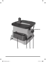
17. Belt Sander
18. Dust Extraction Port
19. Table Angle Knob
20. Throat Plate Storage
21. Wrench Storage
22. Rear Storage
23. Belt Sanding Unit
24. Sanding Belt
25. Sanding Sleeves (5 sizes)
26. Throat Plates (5 sizes)
27. Spindle Nut
28. Spindle Washers
29. Table Insert
30. Wrench
31. Sleeve Drums (4 sizes)
32. Spindle
33. Spindle Knob
Intended Use
Mains-powered bench-mounted sanding machine that can be fitted with either a rotating and
height oscillating sanding sleeve drum or a sanding belt unit. For sanding curved and straight
surfaces on intricate as well as larger workpieces. Tilting front section table enables edge
work, typically chamfering.
Before Use
WARNING:
Ensure the tool is disconnected from the power supply before attaching or
changing any accessories, or making any adjustments.
Bench Mounting
If the spindle sander is to be used in a permanent position, it is recommended that you secure
it to a rigid work surface.
• Use the Bench Mounting Holes (11) in the base as a template to mark and drill four holes
in your intended mounting surface (ie workbench). Secure the spindle sander into position
using large bolts, washers and nuts (not supplied) (Figure I)
• If the spindle sander is intended to be more portable, fix a board to the base which can be
easily clamped and removed from various mounting surfaces
• If using bolts make sure they are long enough to penetrate the workbench or board
sufficiently for a secure fix
Note:
Use nylon insert lock nuts or spring washers in the fixings to prevent vibration from
loosening the fixings.
Note:
Never use bolts that require force to push through the Bench Mounting Holes as these
may crack the plastic body, as will over-tightening the fixings.
Dust Extraction
It is recommended that the spindle sander is used with a dust extraction system for a cleaner
and safer work environment.
1. Attach the hose from the dust extraction system to the Dust Extraction Port (18) and
ensure it is secure
2. For greatest efficiency, activate the dust extraction system before turning on the
spindle sander
Belt Sander Mode
1. To remove the spindle sander components, unscrew the Spindle Nut (27) using the
Wrench (30) and remove the fitted Spindle Washer (28), Sleeve Drum (31), Throat Plate
(26) and Table Insert (29)
2. Store the spindle sander components into the built-in storage areas of the main body;
these are Washer Storage (14), Drum Storage (15), Throat Plate Storage (7 & 20) and Rear
Storage (22).
3. Fit the Belt Sanding Unit (23) into the recess of the Fixed Table (6) as shown and secure in
position with the Spindle Knob (33)
4. If required for operation, fit the Workpiece Stop (3) using the Workpiece Stop Wing Nut (5)
5. If no Sanding Belt (24) is fitted, move the Belt Release Lever (2) towards the Spindle Knob
to allow a belt to be fitted. This is a spring-loaded mechanism under some tension so
ensure movement is controlled to prevent damage
6. Fit a belt, lining it up level at the correct height on the main roller of the Belt Sanding
Unit ensuring the orientation of the belt is correct (Image A) and matches the direction
of the arrow
7. Move the Belt Release Lever back towards the Belt Tracking Knob (1) to secure the belt
8. Reconnect power to the tool and switch on but monitor the tracking of the belt to ensure it
is correct. Switch off immediately if the tracking of the belt is incorrect and it is moving up
or down on the roller
Tracking adjustment
Adjust the belt tracking using the Belt Tracking Knob. If the belt is moving slowly from its set
position, make small adjustments using the Belt Tracking Knob. If the tracking is very poor
each time it is switched off, use the Belt Release Lever so you can re-adjust the belt height
back to the correct height before using the Belt Tracking Knob to make adjustments.
• To increase the height of the belt, turn the Belt Tracking Knob clockwise. To decrease the
height of the belt, turn it anti-clockwise
• There may be an adjustment range on the Belt Tracking Knob where the belt tracks
consistently. Always aim for the middle of this adjustment range for optimal centralised
tracking even under load
Note:
The belt will be damaged if it rubs against the surface in the recess of the Fixed Table
because of incorrect tracking. It is easier to adjust the tracking that causes the belt to move
upwards than downwards as going upwards will not damage the edge of the Sanding Belt.
Make a large adjustment clockwise on the Belt Tracking Knob and then gradual adjustments
anti-clockwise to bring the height back down.
Spindle Sander Mode
Selecting the right grade of sanding sleeve
• Sanding sleeves are available in a variety of different grades: coarse (80 grit), medium
(150 grit) and fine (240 grit)
• Use a coarse grit to sand down rough finishes, medium grit to smooth the work, and fine
grit to finish off
• Always use good quality sanding sleeve to maximise the quality of the finished task
• It is advisable to do a trial run on a scrap piece of material to determine the optimum
grades of sanding sleeve for a particular job. If there are still marks on your work after
sanding, try either going back to a coarser grade and sanding the marks out before
recommencing with the original choice of grit, or try using a new piece of sanding sleeve
to eliminate the unwanted marks before going on to a finer grit and finishing the job
Fitting a sanding sleeve
1. Remove the Belt Sander (17) by unscrewing and removing the Spindle Knob (33) and
lifting the Belt Sander from the Fixed Table (6). Store in the Rear Storage (22)
2. Select the correct compatible parts using the throat plate chart
3. Install the components as shown (Figure II)
4. Tighten the Spindle Nut (27) using the Wrench (30) to ensure the sanding sleeve does not
slip in operation. Do not over-tighten
5. If required for operation, fit the Workpiece Stop (3) using the Workpiece Stop Wing Nut (5)
189888_Manual.indd 8
11/12/2018 13:35
Summary of Contents for TSPST450
Page 2: ...2 5 4 3 2 1 6 8 10 9 7 11 15 17 16 12 13 14 189888_Manual indd 2 11 12 2018 13 35...
Page 3: ...3 18 19 20 21 22 189888_Manual indd 3 11 12 2018 13 35...
Page 4: ...4 25 33 30 31 24 23 29 26 28 27 189888_Manual indd 4 11 12 2018 13 35...
Page 5: ...A D B E C F II 27 28 32 26 29 25 31 I 189888_Manual indd 5 11 12 2018 13 35...


