background image

Aspirante xr

13

WARNING!

The outlet of the shower acts as a 

vent and must NOT be connected to 

anything other than the hose and 

showerhead supplied.

PLUMBING CONNECTIONS
Plumbing to be carried out before wiring

DO NOT use jointing compounds on any pipe 
fittings for the installation.
DO NOT solder fittings near the shower unit 
as heat can transfer along the pipework and 
damage components.
Compression fittings MUST


be used to connect 

to the inlet of the shower. Push-on fittings must 
NOT be used as full engagement cannot be 
guaranteed.

Note:

 An additional stopvalve (complying with 

Water Regulations) MUST be fitted in the mains 
water supply to the shower as an independent 
means of isolating the water supply should 
maintenance or servicing be necessary. If this 
isolator is fitted in a loft space, the loft must 
have a fixed access ladder and be boarded, with 
appropriate lighting from the access point to the 
isolator.

IMPORTANT:

 Before completing the 

connection of the water supply to the inlet 
of the shower, flush out the pipework to 
remove all swarf and system debris. This can 
be achieved by connecting a hose to the 
pipework and turning on the mains water 
supply long enough to clear the debris to 
waste.

Procedure

Turn off water supply either at the mains 
stopvalve or the isolating stopvalve. Connect the 
mains water supply to the inlet of the shower 
via 15mm copper, stainless steel or plastic 
pipe using a 15mm x 15mm elbow or straight 
coupler compression fitting.
DO NOT use excessive force when making these 
connections.
Make sure the backplate is square on the wall 
and tighten the two retaining screws which hold 
it to the wall.
Turn on the mains water supply and check for 
leaks in the pipework connection to the shower.

Note:

 At this stage no water can flow through 

the unit.

Plumbing connections

PLUMBING CONNECTIONS

Summary of Contents for ASPIRANTE XR

Page 1: ... the user IMPORTANT SAFETY ADVICE The shower unit MUST BE switched off at the isolating switch when not in use This is a safety procedure recommended for all electrical appliances The showerhead and hose supplied with this product are a safety critical part of your shower Failure to use genuine Triton parts may cause injury and invalidate your guarantee ...

Page 2: ...ected to any tap or fitting other than those specified This appliance must not be connected to the water mains supply and not connected by a hose set A suitable double pole isolation switch for supply disconnections must be incorporated in the fixed wiring circuit in accordance with current wiring rules See Electrical Installation section for further details Minimum inlet pressure 0 08 metres 0 78...

Page 3: ...tions or any particular regulations as specified by Local Water Company or Water Undertakers and should be in accordance with BS EN 806 2 2 The supply pipe must be flushed to clear debris before connecting to the shower unit 2 3 DO NOT solder pipes or fittings within 300mm of the shower unit as heat can transfer along the pipework and damage components 2 4 DO NOT fit any form of outlet flow contro...

Page 4: ...r b During winter the mains water supply will be cooler than in the summer so the flow rate will vary between seasons at any one temperature setting At different times of the year you may have to adjust the position of the temperature control to maintain your desired temperature setting c The stabiliser valve minimises variations in shower temperature during mains water pressure changes If changes...

Page 5: ... shower 18 19 Operating functions 20 Cleaning 21 Instructions for installers and service engineers only 22 Fault finding 23 24 Spare parts 25 Guarantee service policy etc rear cover CONTENTS Page To check the product suitability for commercial and multiple installations please contact Triton s specification advisory service before installation Please see back of book for contact information PRODUC...

Page 6: ...Solenoid valve 11 Guide pockets 12 Can and element assembly 13 Thermal cut out main 14 Earth connection 15 Pressure relief device 16 Outlet temperature limiter 17 Trimplate Inside cover fig 2 18 Cover tags 19 Control PCB 20 Start Stop switch 21 Neon lens Main components MAIN COMPONENTS WARNING WARNING Fig 1 Fig 2 Note Not all wiring shown for reasons of clarity 1 2 3 4 5 6 6 7 8 9 10 11 11 11 12 1...

Page 7: ...witch off the whole installation at the mains supply and remove the correct fuse 3 The shower must be connected to its own independent electrical circuit IT MUST NOT be connected to a ring main spur socket outlet lighting circuit or cooker circuit 3 1 The electrical supply must be adequate for the loading of the unit and existing circuits 4 Check your consumer unit main fuse box has a main switch ...

Page 8: ...n a bath or shower cubicle It should be readily accessible to switch off after using the shower 7 Where shower cubicles are located in any rooms other than bathrooms all socket outlets in those rooms must be protected by a 30mA RCD 8 The current carrying capacity of the cable must be at least that of the shower circuit protection see Table B 8 1 To obtain full advantage of the power provided by th...

Page 9: ...ocal water company or consult a competent plumber During periods of high ambient temperatures it may be necessary to select a low power setting to achieve your preferred shower temperature The water supply can be taken from a cold water storage cistern provided there is a minimum head of ten metres fifteen metres for the 10 5kW rated shower above the showerhead It must be an independent supply to ...

Page 10: ... tray then a double check valve or similar must be fitted in the supply pipework to prevent back flow Pressure relief safety device A pressure relief device PRD is designed into the shower unit which complies with European standards The PRD provides a level of appliance protection should an excessive build up of pressure occur within the shower DO NOT operate the shower with a damaged or kinked sh...

Page 11: ...ng a feed pipe from the rear bottom or side the centre of the inlet valve to the wall surface is 21mm fig 10 Note If entry is from the rear the nut of the compression fitting will be partially behind the surface of the wall fig 10 This area MUST be left clear when plastering over the pipework in order to make the nut accessible for future adjustments IMPORTANT Always seal around the incoming pipew...

Page 12: ... head protruding 6mm out from the wall Hook the backplate over the bottom screw and fit the top fixing screw into position Do not fully tighten the screws at this stage as the fixing holes are elongated to allow for out of square adjustment after the plumbing connections have been completed Note If replacing an existing shower unit a replacement installation trim is a vailable to help accommodate ...

Page 13: ...ave a fixed access ladder and be boarded with appropriate lighting from the access point to the isolator IMPORTANT Before completing the connection of the water supply to the inlet of the shower flush out the pipework to remove all swarf and system debris This can be achieved by connecting a hose to the pipework and turning on the mains water supply long enough to clear the debris to waste Procedu...

Page 14: ...minal marked L IMPORTANT Fully tighten the terminal block screws and make sure that no cable insulation is trapped under the screws Loose connections can result in cable overheating Note The supply cable earth conductor must be sleeved The outer sheath of the supply cable must be stripped back to the minimum The supply cable must be secured either by routing through conduit or in trunking or by em...

Page 15: ...lty arise recheck the points above While applying slight pressure to the front cover secure in position with the three retaining screws Fit the flexible hose to the shower outlet making sure the outlet of the hose is directed to waste Check the supplied sealing washer is in place DO NOT attach the showerhead at this stage Before turning on the electric and mains water supplies to the shower make s...

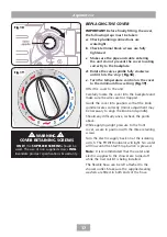
Page 16: ...lectricity to the shower at the isolating switch The water will cease to flow Unscrew the three retaining screws once again and lift the cover from the backplate Attached to the display PCB inside the cover is a 10 way ribbon cable The ribbon cable connector must be plugged into the socket located at the right of the power PCB situated inside the unit fig 17 Note the cable connector can be fitted ...

Page 17: ...or adjustment may be necessary to align the knob and spindle Should any difficulty arise recheck the points above While applying slight pressure to the front cover secure in position with the three retaining screws Turn the electric supply back on at the isolating switch The POWER indicator will light No water will flow until the Start Stop button is pressed Note It is recommended that the water a...

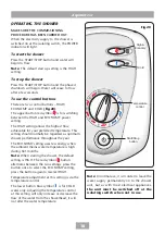
Page 18: ...arded as optimum shower performance throughout the year The ECONOMY setting uses less energy when the ambient mains water temperature is high during hot months Note When starting the shower the default setting is HIGH The red symbol button alternates between the two settings press the button once to select the ECONOMY setting press the button again to reselect HIGH Temperature adjustment at this s...

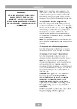
Page 19: ...the flow of water through the shower To increase the shower temperature Turn the temperature control clockwise to decrease the flow of water through the shower Note It is advisable to be certain that the showering temperature is satisfactory by testing with your hand before stepping under the showerhead There will always be a time delay of a few seconds between selecting a flow rate and the water ...

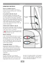
Page 20: ...en the START STOP button is pressed power is switched off to the elements Water will continue to flow for a few seconds flushing out any remaining hot water This makes sure the next immediate user will not receive a slug of hot water if standing under the showerhead when starting the shower Temperature limiter During normal operation if an overheat temperature is sensed power to the elements will ...

Page 21: ...n switch to avoid the shower being accidentally switched on Triton recommends that all products are cleaned using warm soapy water WARNING DO NOT use abrasive or aggressive chemical cleaning products as this may damage the product surface finish and invalidate your guarantee ...

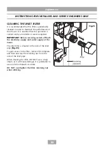
Page 22: ...ater supply at the mains The inlet filter is situated in the side of the inlet pipe fig 23 To gain access to the filter remove the trimplate and then unscrew the retaining nut from the side of the inlet pipe When cleaning the filter DO NOT use a sharp object as it will cause damage It is preferable to use an old toothbrush or similar DO NOT overtighten the filter retaining nut when refitting Fig 2...

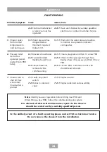
Page 23: ...e local Electricity Supply Company 1 2 1 Have unit checked Ring Customer Service 2 1 1 Increase the flow rate via temperature control 2 1 2 Blocked showerhead clean blocked sprayplate 2 2 1 Check if stop valves are fully open Check if blockage in inlet filter 2 3 1 Switch to economy power setting and readjust flow rate to give required temperature 3 1 1 See Water too hot causes 2 1 2 2 and 2 3 and...

Page 24: ...ked by suitably qualified electrician or contact Customer Service 5 1 1 Wait until the water pressure resumes to normal Low pressure indicator extinguishes 6 1 1 Clean sprayplate and then fit a new PRD 6 2 1 Check for free passage through hose Replace hose if necessary and then fit new PRD 6 3 1 Fit new PRD Commission unit with showerhead removed 7 1 1 Replace switch 7 2 1 Replace solenoid valve a...

Page 25: ...back scheme DTS registration number 9659 All our electric products are labelled accordingly with the crossed out wheeled bin symbol This indicates for disposal purposes at end of life that these products must be taken to a recognised collection points such as local authority sites local recycling centres this will be free of any charges Do not return to Triton Showers To purchase a genuine Triton ...

Page 26: ...Aspirante xr 26 ...

Page 27: ...Aspirante xr 27 ...

Page 28: ... credit debit card excluding American Express or Diners Card Payment can also be made by pre payment of a pro forma invoice by cheque or postal order Telephone orders are based on information given during the call Before contacting Triton please verify your requirements using the Triton website or your professional installer Triton cannot accept liability for incorrect part identification TRITON S...

Reviews: