background image

pag. 4

1.1 USE OF ANTIFREEZE LIQUID

1.2 FEATURES OF UNDER FLOOR 

HEATING SYSTEMS

If you smell gas:

- do not operate electrical appliances
- extinguish any fires 
- close the stopcock upstream of the meter
- open the windows and ventilate the room
- call your local authorised engineer

Do not store or use flammable materials near the boiler.

Do not obstruct intake/exhaust terminals.

To guarantee boiler efficiency and correct operation, it is
imperative to have yearly maintenance, and combustion
analysis every two years, carried out by qualified
engineers, and to have the system booklet prepared, as
stipulated by law.

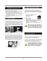
It is forbidden to touch the boiler either with bare feet
and/or with wet parts of the body.

In order to clean the outside parts, turn off the boiler turn
off the power at the isolating switch. Clean with a damp
cloth. Do not use detergents and/or harsh liquids, or toxic
products.

In order to carry out any work on the boiler, do not mount
it on chairs, stools, ladders or unstable stands.

Before carrying out any work on the boiler always turn
the power off at the isolating switch

The user is forbidden to carry out any maintenance work
on the boiler that must be carried out by a specialised
engineer.

In the case of structural work or maintenance near the
pipes, flue systems or any accessories, switch off the
appliance and, when the work is completed, have the
system checked by a qualified engineer to ensure the
system is in good working order.

1.3 SAFETY ADVICE

In floor systems, the use of plastic pipes without
protection against penetration of oxygen through
the walls can cause corrosion of the system's
metal parts (metal piping, boiler, etc), the forma-
tion of oxides and bacterial agents.

To prevent this problem, it is necessary to use pipes with an
"oxygen-proof barrier", in accordance with standards DIN
4726/4729.

If pipes of this kind are not used, keep the system separa-
te by installing heat exchangers or those with a specific
system water treatment.

In floor systems, a system safety thermostat must
be installed to protect against overtemperature
calibrated at around 45°C (see wiring diagram on
page 14).

TRIANCO is not liable for damage caused to the unit or the
system due to failure to comply with the above.

If antifreeze substances are used in the
system, check carefully that they are compati-
ble with the aluminium that forms the body of
the boiler.

In particular, DO NOT USE ordinary ETHYLENE
GLYCOL, since it is corrosive in relation to aluminium
and its alloys, as well being toxic.
Trianco suggests the use of suitable antifreeze products
and in the correct dose, which will prevent rust and
incrustation taking place.

Periodically check the pH of the water-antifreeze mixtu-
re of the boiler circuit and replace it when the amount
measured is lower than the limit stipulated by the manu-
facturer.

DO NOT MIX DIFFERENT TYPES OF ANTIFREEZE

TRIANCO  is not liable for damage caused to the boiler
or system as a result of the use of incorrect antifreeze or
additive substances.

Summary of Contents for OPTIMA 28 CB

Page 1: ...OPTIMA 28 CB AND 28 SB WALL MOUNTED GAS BOILERS INSTALLATION INSTRUCTIONS...

Page 2: ...25 15 Examples of installation pag 26 16 Accessories pag 27 17 Periodic appliance maintenance and cleaning pag 28 18 Short parts list pag 31 19 Balanced flue kits pag 33 1 Warnings pag 3 1 1 Use of an...

Page 3: ...e without the express written permission of Trianco Ltd could invalidate the appliance warranty and infringe the Gas Safety Installation and Use Regulations Incorrect installation may cause harm to pe...

Page 4: ...engineer to ensure the system is in good working order 1 3 SAFETY ADVICE In floor systems the use of plastic pipes without protection against penetration of oxygen through the walls can cause corrosio...

Page 5: ...comfort in all conditions DOMESTIC HOT WATER DRAW OFF CB MOD When calling for domestic hot water the boiler by means of an appropriate sensor automatically switches over in order to guarantee supply o...

Page 6: ...5 Class of NOx emissions EN 483 Cl 5 5 5 5 Combustion efficiency 97 9 97 9 97 9 97 9 Flue Gas mass range at nominal capacity kg h 43 5 43 5 43 5 43 5 Residual flue gas discharge head Pa 73 73 73 73 Ga...

Page 7: ...m Filling Valve 14 Domestic water pressure switch 15 Domestic water temperature sensor 16 Bypass 17 Delivery temperature sensor 18 Three way valve 19 Condensation Trap A Heating Flow B Domestic hot wa...

Page 8: ...3 bar The pressure relief discharge pipe should be not less than 15mm dia run continuously downward and preferably over a drain It should be routed in such a manner that no hazard occurs to occupants...

Page 9: ...ick opening window etc 300 Vertical Flues minimum distance to edge of terminal mm P Above the roof level to base of terminal 300 Q From adjacent wall to flue 300 R From adjacent opening window 1000 S...

Page 10: ...t rawlplugs and mounting bolts 2 Fix the boiler to the wall using the wall mounting bracket 3 Pass the terminal through the wall and fit the internal wall seal to the terminal 4 Fit the 60mm black sea...

Page 11: ...SUPPLIED EXTRA PIPES CAN BE PURCHASED TO EXTEND TO 4 MTRS L H SIDE OUTLET HORIZONTAL BALANCED FLUE HIGH LEVEL HORIZONTAL BALANCED FLUE MAX MIN WALL THICKNESS IS WITH KIT SUPPLIED EXTRA PIPES CAN BE P...

Page 12: ...all sections are pushed firmly home Secure bot tom section to boiler with clamp 7 Fit a roof flashing sleeve to the roof not supplied and insert Vertical Flue Terminal through flashing from the outsi...

Page 13: ...pag 13 A B C D A B 2500mm MAX C D 4000mm MAX NOTE For each additional elbow reduce straight lengths by the relevant elbow dimension 90 1500mm and 45 750mm 90 BEND 1000mm 45 BEND 750mm...

Page 14: ...ower them both together fig 5 3 5 ACCESS TO ELECTRICAL PANEL FOR CON NECTING ADDITIONAL UNITS CONTROL PANEL BOILER CONTROL PANEL COVER fig 5 2 fig 5 3 V2 V1 fig 5 1 In order to connect any external co...

Page 15: ...0 VAC Configurable connection 230 VAC Ionisation probe Gas valve mains gas 230 VAC Ignition electrode Ignition transformer 230 VAC AC 24V Transformer Fan motor 2 3 1 2 3 1 4 2 3 1 4 5 2 3 1 4 5 6 2 3...

Page 16: ...INARY CHECKS TO BE CARRIED OUT BEFORE APPLIANCE START UP The water pressure is checked periodically on the pressure gauge described in paragraph 7 1 In order to reset the pressure to within the preset...

Page 17: ...de with knobs B and C Heating and domestic hot water temperatures remain unchanged even after power supply fai lure MODE BUTTON The MODE button makes it possi ble to switch from summer to winter opera...

Page 18: ...is play returns to reading 1 in all cases after some minutes the boiler temperature display is reset RESET BUTTON RESETTING THE APPLIANCE After an operating irregularity the boiler stops for safety re...

Page 19: ...b3 not used b4 letter of outside temperature C b5 not used b6 not used b7 second zone circuit temperature C C1 letter of ionisation current value A C2 letter of number of fan revolutions thousands an...

Page 20: ...the lower section the protecti ve cover connect the wires to the probe and the boiler following the wiring diagram on page 14 20 20 15 10 5 0 5 10 15 20 30 40 50 60 70 80 90 2 n 4 6 8 10 12 14 16 18...

Page 21: ...icult to use the heating system eg in summer or with a floor radiant panel system it is possible to use the domestic hot water circuit by proceeding as follows rotate the control panel forward para 5...

Page 22: ...what is described below If the values found are different proceed as follows Turn gas valve capacity regulator 2 figure 10 3 clockwise to increase anticlockwise to decrease value of CO2 reading given...

Page 23: ...ermostat or deactivate the hea ting by pressing the MODE button LED F goes out This will ensure that the antiseize function and other functions designed for the appliance safety and com fort still ope...

Page 24: ...URE CODE DISPLAY A fault or temporary failure is indicated by a three figure code appearing on the display Two of them can be presen ted on the display and then the code is indicated showing alternati...

Page 25: ...sconnected not used 82 Incompatible LPB address not used 91 Fault inside board 92 Fault inside board 100 Incorrect configuration of clocks in connection with RVA not used 110 Fault due to overtemperat...

Page 26: ...M CR TA SI OPTIMA SB MOD SE External probe CR TA QAA73 programmer room thermostat YD 3 way valve for hot water production TB Domestic hot water tank temperature probe SI high temp safety therostat fo...

Page 27: ...remote control according to weekly and hourly setting with yearly date setting which has functions of monitoring boi ler and programming zone sensor alarm indicators and advanced diagnostics fig 16 1...

Page 28: ...er is cool Ensure that both the gas and electrical supplies to the boiler are isolated Caution All gaskets removed must be checked and possibly replaced if they are damaged or worn To access inside of...

Page 29: ...17 8 Remove pneumatic and electrical fan connections and disconnect gas pipe Remove nuts E1 unthread MIXER E FAN F unit fig 17 6 Extract internal choke G and inspect O ring with the aid of a brush or...

Page 30: ...flue H from boiler shell fig 17 6 and with the aid of a brush and vacuum cleaner clean between the exchange rungs fig 17 9 When the parts are replaced take care to reinsert them in the correct order p...

Page 31: ...ON ELECTRODE BFE01064 23 CENTRIFUGE FAN W150 4 32 IMMERSION SENSOR S300 1 36 CIRCULATOR P158 37 AUTOMATIC ESCAPE VALVE G207 1 39 WATER GAUGE G603 3 40 GAS VALVE UNIT GRVAL001 41 CIRCULATOR CONSENSUS D...

Page 32: ...1001 19 IGNITION ELECTRODE BFE01019 20 ELECTRODE GASKET CFG01009 21 DETECTION ELECTRODE BFE01064 23 CENTRIFUGE FAN W150 4 32 SENSOR S300 1 35 CIRCULATOR P158 35 1 AUTOMATIC ESCAPE VALVE G207 1 36 MINI...

Page 33: ...1 3 510028 100mm seal 1 Item Part No Description Qty 1 510023 90 concentric bend 1 2 510027 60mm seal Blue 1 3 510028 100mm seal 1 Item Part No Description Qty 1 510024 45 concentric bend 1 2 510027 6...

Page 34: ......

Page 35: ......

Page 36: ...service division is notified promptly of any defects Under the terms of guarantee the appliance must be made available for service during normal working hours Monday to Friday weekend work not accep...

Reviews: