


1
2
1
2
3-1
3-2
B
A
1
2
1
2
A
B
Self-Tapping Screw
Vertical
Window
Opening
Horizontal Window
Opening
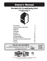
4-1
4-2
4-3
4-4
Ceiling Panel
(From Below)
Ceiling Panel
(From Above)
Exhaust Panel
7
Installation
(continued)
3
Exhaust Duct Connection
Note:
The SRCOOL18K and SRCOOL24K both contain two exhaust ducts (one for each warm air exhaust) and two exhaust duct adapters.
Repeat steps
3-1
and
3-2
install the second exhaust duct and adapter.
3-2
Connect the other end of the exhaust duct
A
to the exhaust duct adapter
B
. Align the
duct with the circular adapter opening, push the duct inward and turn the duct clockwise
until it screws into the adapter solidly. Repeat for the second exhaust duct tube.
If you plan to connect the exhaust duct to a drop ceiling, proceed to step
4
. If you plan to
connect the exhaust duct to a window, proceed to step
5
.
4
Drop Ceiling Exhaust Connection
Note:
The SRCOOL18K and SRCOOL24K both contain two adjustable exhaust panels (one for each warm air exhaust duct). Repeat steps
4-1
through
4-4
to install the second exhaust panel.
Warning: Some ceilings may require modified installation procedures. The user must determine the fitness of hardware
and procedures before installing. The procedures described in this manual may not be appropriate for all applications. The
exhaust panels are not designed to be installed side-by-side.
4-3
Slide the ceiling panel out of the way and place the exhaust panel inside the ceiling space.
Allow the exhaust panel to rest on top of the ceiling grid.
Note:
There must be at least 10 inches (25.4 cm) of open space above the exhaust panel
to allow adequate airflow.
4-4
Slide the ceiling panel back into place so that it adjoins the exhaust panel and closes any
gaps in the ceiling. A tight seal will permit maximum cooling efficiency. If the installation
is permanent, trim the ceiling panel so it doesn’t overlap the ceiling grid. Repeat for the
second exhaust duct tube.
Note:
The flexible exhaust duct can extend to a maximum length of 118 inches (300 cm).
Provide the straightest, shortest path available. Excessive bending or stretching of the duct will
reduce cooling efficiency.
After completing step
4
, proceed to step
6
.
4-1
Choose a removable drop ceiling panel near the unit to provide the straightest, shortest
path available for the flexible exhaust duct. Measure the width of the ceiling panel,
including the portion that rests on the ceiling grid. Combine the two sections of the
adjustable exhaust panel, then adjust the exhaust panel to match the width of the ceiling
panel. After the exhaust panel is set to the correct width, use the included self-tapping
screw to lock it in place.
Note:
The exhaust panel can adjust from 20.5 to 49.2 inches (52.1 to 104.1 cm).
Certain installations may require trimming the exhaust panel for a proper fit.
4-2
Insert the exhaust duct adapter into the oblong hole in the adjustable exhaust panel. The
adapter will snap into place.
3-1
Connect the flexible gray exhaust duct tube
A
to the warm air exhaust vent on the rear
panel of the unit
B
. Align the duct with the circular vent opening, push the duct inward
and turn the duct clockwise until it screws into the exhaust vent solidly. Repeat for the
second exhaust duct tube.