background image

5

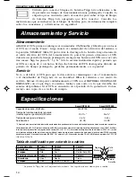
Basic Operation

Switches

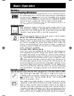
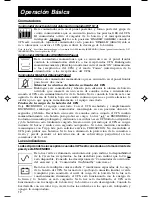
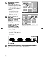
System Enable Switch (DIP Switch #4)

This switch is on the back panel in the set of 4 switches next to
the UPS’s DB9 ports. It activates the battery charger and intelligent
microprocessor.  Always leave it in the “ENABLE” (UP) position
when your UPS is plugged in. Set the switch to “DISABLE” (DOWN)
only if you store or ship your UPS (to reduce battery drain).

Note: the “

” light will flash until you engage the ON/Standby Switch to activate the

“ON” mode (power ON at the UPS receptacles).

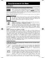
ON/Standby Switch

This momentary switch on the front panel controls power to the
UPS receptacles. Engage it momentarily and release it to toggle
between the “ON” mode (power ON at the UPS receptacles) and
“Standby” mode (power OFF at the UPS receptacles).

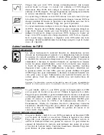
Mute/Test Switch

Use this momentary switch on the front panel to do two things:

Silence the UPS On Battery alarm

Engage this switch and release it to silence the UPS On Battery
alarm, a series of short beeps that sounds intermittantly when
the UPS is providing AC power from battery. Note: when the
battery is nearly depleted, the Low Battery alarm, a continuous
beep that cannot be silenced, will alert you to immediately shut
down connected equipment.

Test your UPS’s battery charge

Leave your connected equipment ON. With your UPS plugged in
and completely turned ON, engage this switch; hold it there for
5 seconds and release it. You will hear a series of short beeps as
the UPS momentarily switches to battery to test its charge. The

” light will turn ON and the alarm (a long, continuous beep)

will sound if your UPS fails a self-test and/or the UPS battery is
less than fully charged. If this occurs, let the UPS charge for 12
hours and perform a second self-test. If the light continues to stay
on, contact Tripp Lite for service. CAUTION: Do not unplug your
UPS to test its batteries. This will remove safe electrical grounding
and may introduce a damaging surge into your network connections.

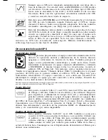
Indicator Lights

Light descriptions apply when the UPS is plugged into a wall outlet and turned ON.

This green light will shine 

constantly

 to indicate AC power is

available at the receptacles. It will 

flash

 to indicate AC power is

not available. (See “System Enable Switch” and “On/Standby
Switch” descriptions  above.)

This multi-colored light displays 7 separate UPS battery charge
conditions. It will turn from red (low) to yellow (medium) to green
(full) to show you the level of battery charge. If the light is
constant, your UPS is operating from line power, and the battery is
charging. If the light is flashing, your UPS is operating from battery
power, and the battery is discharging. When the light flashes red,
close any files you are working on and shut down your computer.

9905248 DON'T ARCHIVE!!! 2200-3000 VA 230V SmartPro OM.p65

6/20/00, 10:13 AM

5

Summary of Contents for Smart INT 2200

Page 1: ...Basic Operation p 5 7 Storage Service p 7 Specifications p 7 Safety p 2 Warranty Insurance p 6 1111W 35thStreet Chicago IL 60609 USA CustomerSupport 773 869 1234 www tripplite com Owner sManual Smart...

Page 2: ...ntly alter the performance of a life support device Do not connect surge suppressors to the output of your UPS This may damage your UPS and will void both the surge suppressor and UPS warranties Batte...

Page 3: ...youconnecthousehold appliances laser printers or surge suppressors Cords and receptacle adapters are available from TrippLitetoaccommodatemostoutletconfigurations If rewiring is necessary refer to the...

Page 4: ...computers Connect them to the DB9 ports labeled LAN 2 2 which provide basic contact closure shutdown capabilities using the black cables that came with your UPS Set their corresponding LAN Interface D...

Page 5: ...quipment ON With your UPS plugged in and completely turned ON engage this switch hold it there for 5 seconds and release it You will hear a series of short beeps as the UPS momentarily switches to bat...

Page 6: ...on the UPS are also used to connect your UPS to a workstation or server Use with Tripp Lite software and cabling to automatically save open files and shut down equipment during a blackout This port us...

Page 7: ...attery Runtime Half Load Full Load Minutes 27 11 23 7 Battery Recharge Time 2 4 hrs 2 4 hrs Approvals UL CE UL CE BatteryRuntimeforthismodelcanbeincreasedwiththeadditionofoptionalexternalbatterypacks...

Page 8: ...p 10 11 Operaci n b sica p 12 14 Almacenamiento y servicio p 14 Especificaciones p 14 Seguridad p 9 Warranty Insurance p 6 1111W 35thStreet Chicago IL 60609 USA DepartamentodeAsistenciaalCliente 773...

Page 9: ...mente el rendimiento del dispositivo de sustentaci n de la vida No conecte supresores de sobrevoltaje a la salida del UPS Si lo hace podr a causar da os al UPS y anular las garant as del supresor de s...

Page 10: ...S lo sobrecargar TrippLitetienedisponiblescablesyadaptadoresde recept culos que se ajustan a la mayor a de las configuraciones de salida Si es necesario volver a hacer las conexiones el ctricas consul...

Page 11: ...DB9 rotulados LAN 2 2 que proporcionan capacidades b sicas de apagado de cierre por contacto utilizando los cables negros que se incluyen con su UPS Coloque los conmutadores DIP de interfaz con LAN en...

Page 12: ...ga de la bater a del UPS Deje ENCENDIDO el equipo conectado Con el UPS enchufado y completamente ENCENDIDO embrague este conmutador mant ngalo en esa posici n durante 5 segundos y lib relo Escuchar un...

Page 13: ...nte de Tripp Lite si desea obtener m s informaci n y una lista de los productos SNMP de administraci n de redes y de conectividad que est n disponibles Puertos de cierre por contacto Estos puertos rot...

Page 14: ...11 23 7 Tiempo de recarga de la bater a 2 4 hr 2 4 hr Aprobaciones UL CE UL CE Eltiempodefuncionamientodelabater adeestemodelosepuedeaumentarconlaadici ndebloquesdebater asexternosopcionales Voltajede...

Page 15: ...curit p 16 Warranty Insurance p 6 1111W 35thStreet Chicago IL 60609 USA Assistanceclient le 773 869 1234 www tripplite com Manuel d utilisation SmartPro INT SmartPro XL INT 2 200 3 000 VA Syst mes d U...

Page 16: ...anne ou de compromettre sensiblement la performance d un appareil de maintien des fonctions vitales Ne branchez pas de limiteurs de surtension sur la sortie de votre UPS sous peine d endommager votre...

Page 17: ...mat riel informatique Vous surchargerez votre UPS si vousconnectezdesappareils lectrom nagers des imprimantes laser ou des limiteurs de surtension Descordonsetdesadaptateurssontdisponiblesaupr sde Tri...

Page 18: ...surent les fonctions d arr t de base par fermeture des contacts l aide des c bles noirs qui vous ont t fournis avec votre UPS R glez leurs commutateurs DIP d interface de r seau local correspondants s...

Page 19: ...se trouvant branch sur secteur et enti rement mis sous tension activez ce commutateur maintenez le dans cette position pendant 5 secondes puis rel chez le Vous entendrez une s rie de courts bips sono...

Page 20: ...tactez l assistance client le Tripp Lite pour obtenir de plus amples informa tions et la liste de sproduits SNMP de gestion de r seau et de connectivit disponibles Ports de fermeture des contacts Ces...

Page 21: ...charge pleine charge 27 11 23 7 Temps de recharge de la batterie 2 4 heures 2 4 heures Homologations UL CE UL CE L autonomiedelabatteriepourcemod lepeut treaugment eenajoutantdesblocs batteriesextern...

Page 22: ...allation S 24 25 Grundlegender Betrieb S 26 28 Lagerung und Kundendienst S 28 Technische Daten S 28 Sicherheit S 23 Warranty Insurance p 6 1111W 35thStreet Chicago IL 60609 USA Kundendienst 773 869 12...

Page 23: ...ife Support Systems bewirken k nnte Es darf keine berspannungsschutzeinrichtung an den Ausgang der USV angeschlossen werden Andernfalls k nnen Sch den an der USV verursacht werden wobei die Garantie d...

Page 24: ...schutzeinrichtungenverursachteine berlastungderUSV TrippLiteliefertKabelundSteckbuchsenadapterf rdie meistenSteckdosenkonfigurationen Wenneine Neuverdrahtung erforderlich ist beziehen Sie sich bitte a...

Page 25: ...hnittstelle gesteuert Wenn weitere Computer angeschlossen werden sollen Schlie en Sie diese ber die schwarzen Kabel der USV an die mit LAN 2 2 beschrifteten DB9 Ports an die ein grunds tzliches Aussch...

Page 26: ...SiediesenSchalterbeieingesteckter und vollst ndig EINGESCHALTETER USV halten Sie ihn f nf Sekunden lang und geben Sie ihn wieder frei Sie h ren eine Reihe von kurzen Signalt nen w hrend die USV kurzze...

Page 27: ...werden Kontaktschlie ungsports ber diese mit LAN 2 2 beschrifteten Ports wird die USV auch an die Workstation bzw den Server angeschlossen Verwenden Sie diese mit der Tripp Lite Software und Verkabel...

Page 28: ...nicht abgelaufen ist f gen Sie eine Kopie der Verkaufsbest tigung bei Smart INT 2200 Smart INT 3000 Ausgangskapazit t VA Watt 2200 1700 3000 2400 Batterie Laufzeit Halbe Last Volle Last in Minuten 27...

Reviews: