


3
Install rack handles (supplied)
and mount UPS in standard
19 in. rack using standard rack
hardware (user supplied).
Install your UPS in the lowest rack position possible.
Plug your UPS into
an electrical outlet.
See “Suggested Circuit” in Specifications section
to determine if your model should occupy a 15-amp
or 20- or 30-amp dedicated circuit.
Plug your equipment into
your UPS.
Installation
1
4
2
3
Figure 1
System Enable Switch
(700 - 1400 VA models)
Front Panel
("I" = ENABLE;
"O" = DISABLE)
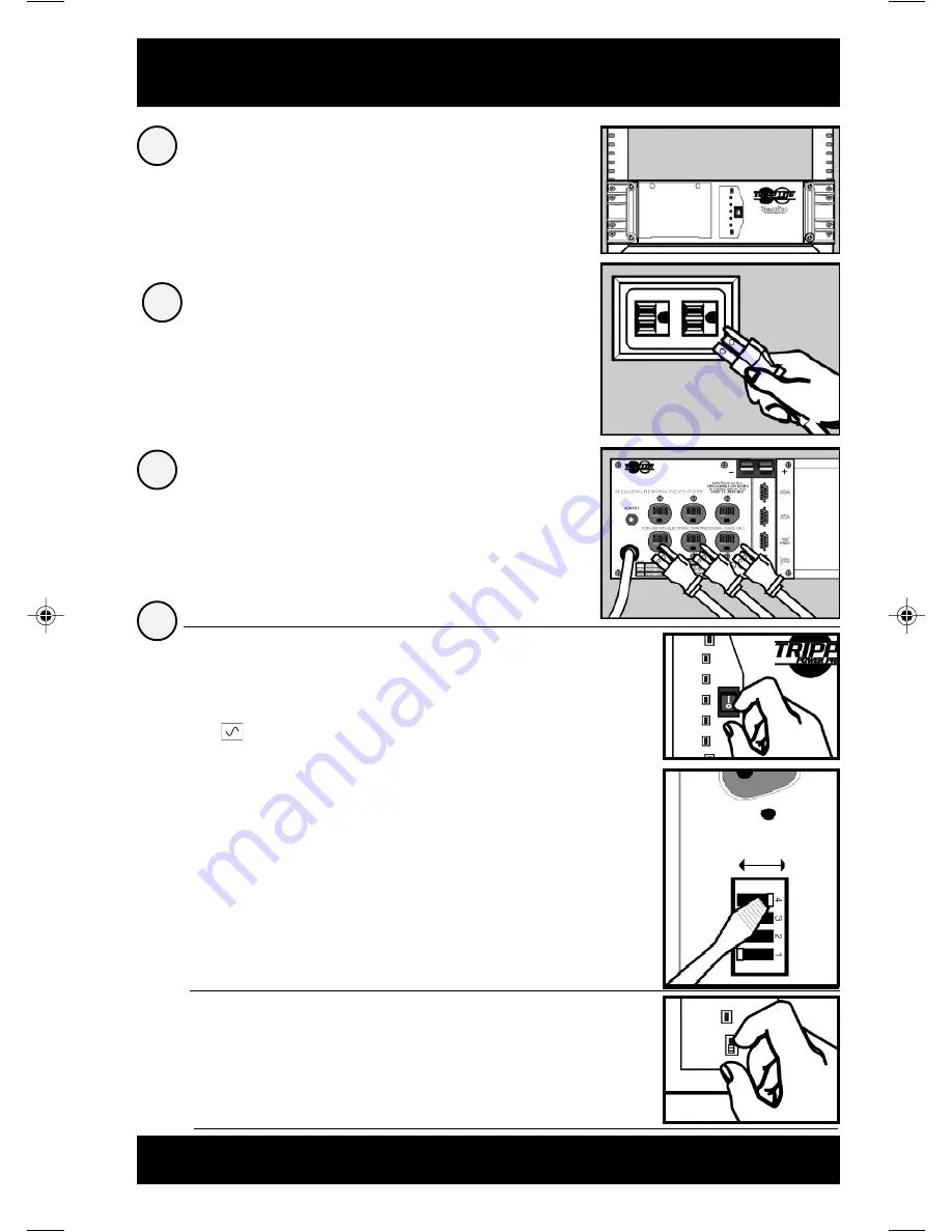
Turn your UPS ON.
Set the System Enable Switch (the
location varies by model, see Figures 1
and 2) to the “ENABLE” position.
This switch activates the battery charger and
microprocessor.
The “
XXX
” light will flash until you engage the
ON/Standby Switch to activate the “ON”
mode.
Engage the momentary ON/Standby
Switch (UPS front panel) and release it
to activate the “ON” mode and supply
power to the UPS receptacles.
(See Figure 3)
DB9 Port Connection (Optional) On Next Page . . .
Your UPS is designed to support only computer
equipment. Connecting household appliances,
laser printers or surge suppressors is not
recommended.
•
•
Figure 3
ON/Standby Switch
(All models)
Front Panel
Figure 2
System Enable Switch
(2200 - 3000 VA models)
Back Panel
DIP Switch #4
DISABLE
ENABLE
9811199 SmartPro Rackmount Owners Manuals.p65
6/22/00, 11:57 AM
3


