


3R
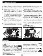
Configuration DIP Switches:
optimize Inverter operation depending
on your application. See Configuration section for setting instructions.
Operating Mode Switch:
controls Inverter operation. See Operation
section for setting instructions.
“LINE”, “INVERT”, “LOAD” LEDs:
intuitive “traffic light” signals
show Inverter operation. They also warn you if the connected
equipment load is too high. See Operation section for instructions on
reading the indicator lights.
"BATT VOLT" or "BATT VOLT/CHRG CURR" LEDs:
on all
models, these three lights will turn on in several sequences to indicate
the approximate charge level of connected batteries. On 2012 and 3012
models, these lights indicate the approximate charge rate of the Inverter
when the Operating Mode Switch is in the “CHARGE ONLY”position.
See Operation section for instructions on reading indicator lights.
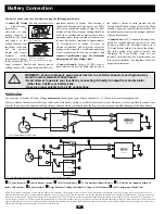
DC Power Terminals:
connect to your battery terminals. See
Battery Connection section for instructions.
Ground Fault Interrupter (GFI) AC Receptacles (not on hardwire
model):
allow you to connect equipment that would normally be
plugged into a utility outlet. Enhancing safety, they feature ground fault
interrupter switches that trip if there is excessive current on the ground
safety wire.
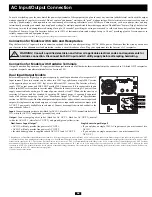
AC Input Cord (not on hardwire model):
connects the Inverter to
any source of utility- or generator-supplied AC power. See AC Input/
Output Connection section for instructions.
Resettable Circuit Breakers:
protect your Inverter against damage
due to overload. See Operation section for resetting instructions.
Remote Control Module Connector:
allows remote monitoring and
control with an optional module included. See remote module owner’s
manual for connection instructions.
Main Ground Lug (front or rear mounted, depending on model):
properly grounds the Inverter to vehicle grounding system or to earth
ground. See Configuration section for instructions.
Multi-Speed Cooling Fan:
quiet, efficient fan prolongs equipment
service life.
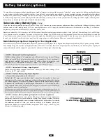
Battery Temperature Sensing Connector (select models only):
prolongs battery life by adjusting charge based on battery temperature.
Use with cable (included). See Configuration section for details.
“AUTO GEN START” Connector (select models only):
this
automatic generator start feature is not typically applicable in
utility/work truck applications. However, for generator-equipped
trucks, it provides crews with the option of quiet power. See “Utilize
Automatic Generator Starter Capability” in the Configuration section
for details.
Hardwire AC Input/Output Terminals (not on corded models):
securely connect the Inverter to vehicle electrical system input and
recommended GFCI receptacle output. See AC Input/Output
Connection.
DC Power Terminal Cover Plate
Hardwire AC Input/Output Cover Plate
Feature Identification
Identify the premium features on your specific model and quickly locate instructions on how to maximize their use.
1
2
3
4
5
6
7
8
9
10
11
12
13
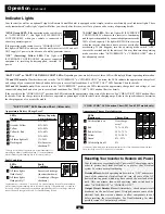
Operation
After configuring, mounting and connecting your Inverter, you can operate
it by switching between the following operating modes as appropriate to
your situation:
AUTO/REMOTE:
Switch to this mode during normal
operational conditions. When service vehicles are
deployed, the Inverter will draw from connected batteries
to supply AC power to connected equipment. This mode
also enables the optional remote control module (included)
to function when connected to the unit. It is fine to leave
the switch in this mode at the end of the day (when service vehicles are
parked) especially when relying upon the remote control as your main
control. Note: when connected to shore power, AC power is not only routed
to the battery charger but passes through to the GFCI outlets or hardwire
terminals (depending on model) as well.
OFF:
Switch to this mode during normal operational
conditions if you want to completely shut down the unit's
inverter, cut-off the remote control module's functionality
and shut off power to the AC outlets or hardwire terminals.
For extended periods of “dry dock” time, switch to this
mode if the Inverter is not plugged into shore power.
CHARGE ONLY:
Switch to this mode when service
vehicles are parked and (optionally) connected to shore
power for extended periods of “dry dock” time, as with
seasonal-use trucks. This mode will enable the unit's
charger, but will disable the unit's inverter. Note: when
connected to shore power, AC power is not only routed to the battery
charger but passes through to the GFCI outlets or hardwire terminals
(depending on model) as well.
Switch Modes
Operation section continued on next page.
Front View (corded models)
2
4
3
5
6
7
8
10
Side Mounted,
Not Shown.
Select models
only.
11
1
9
12
13
Side Mounted,
Not Shown.
Select models
only.
Rear Mounted,
on select
models only
Front View (hardwired model)
2
4
3
10
8
11
1
9
12
13
14
15
16
15
5
16
14
Summary of Contents for APS 2012 INT
Page 11: ...11R...