


TMCM-343 Hardware Manual (V1.07 / 2011-JUN-08)
13
Copyright © 2011, TRINAMIC Motion Control GmbH & Co. KG
7.1.3
TMC428 motion controller
The TMC428 is a high-performance stepper motor control IC and can control up to three 2-phase-
stepper-motors. Motion parameters like speed or acceleration are sent to the TMC428 via SPI by the
microcontroller. Calculation of ramps and speed profiles are done internally by hardware based on the
target motion parameters.
7.1.4
Stepper motor drivers
On the TMCM-343 modules the TMCM246 chips are used. These chips have the stallGuard™ feature.
As the power dissipation of TMC246 chips is very low no heat sink or cooling fan is needed. The
temperature of the chips does not get high. The coils will be switched off automatically when the
temperature or the current exceeds the limits and automatically switched on again when the values
are within the limits again.
The TMCM-343 module is equipped with a circuit that extends the microstep resolution of the TMC246
chips to true 64 times microstepping. The maximum peak coil current of each stepper motor driver
chip is 1500mA.
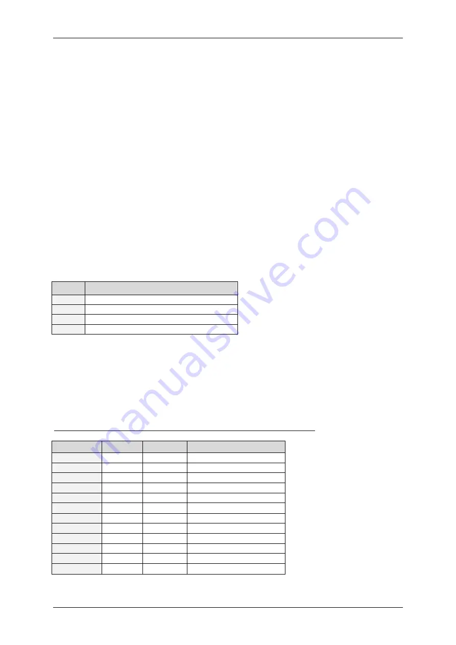
7.2
Power supply
Two different power supplies have to be provided for the TMCM-343: +5VDC for the module
functionality and +7… 34VDC for the motor supply. Please use all listed pins for the power supply
inputs and ground parallel.
Pin
Function
1, 3
+5V DC (+/- 5%), I
max
= 50mA power supply
2, 4
Ground
5, 7, 9
+7… 34V DC motor power supply
6, 8, 10 Ground
Table 7.1: Pinning of power supply
7.3
Motor connection
Never connect or disconnect the motors while the TMCM-343 Module is switched on. Doing this
will destroy the driver ICs!
The TMCM-343 controls up to three 2-phase stepper motors.
Table 7.2 shows how to connect the three motors with the 68-pin connector:
Pin Number Direction
Name
Motor Numbers and Coils
20
out
Motor0_A0
Motor #0, Coil A0
22
out
Motor0_A1
Motor #0, Coil A1
24
out
Motor0_B0
Motor #0, Coil B0
26
out
Motor0_B1
Motor #0, Coil B1
28
out
Motor1_A0
Motor #1, Coil A0
30
out
Motor1_A1
Motor #1, Coil A1
32
out
Motor1_B0
Motor #1, Coil B0
34
out
Motor1_B1
Motor #1, Coil B1
36
out
Motor2_A0
Motor #2, Coil A0
38
out
Motor2_A1
Motor #2, Coil A1
40
out
Motor2_B0
Motor #2, Coil B0
42
out
Motor2_B1
Motor #2, Coil B1
Table 7.2: Pinout for motor connections


