


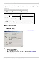

PD-013-42 / TMCM-110-42 Manual (V1.24/2011-NOV-25)
22
Copyright © 2011, TRINAMIC Motion Control GmbH & Co. KG
and very exact movements, due to the high microstepping resolution. For most dynamic operation choose
mode 0 or the combined modes 3 and 4 (which use mode 1 or 2 for slow movements and switch to mode
0 at a defined velocity).
8.2.2
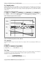
Motor velocity
If you need a high velocity in a given application it is necessary to understand limitations due to supply
voltage and motor inductivity. Please refer to your motor data sheet and choose the chopper mode
adequate. Chopper mode 0 allows maximum motor velocity.
8.2.3
Chopper Modes 0 (SPI / Default Mode) and 1 (PWM)
In these two modes the maximum supply voltage (V
S
) of the motor must not exceed 22-25 times the
nominal motor voltage (V
N
), regarding the multiplication of I
COIL, MAX
and R
MOTOR
. A higher value would lead to
an excess of motor rating.
The minimum supply voltage has to be above two times the nominal motor voltage.
MOTOR
MAX
COIL
N
N
S
N
R
I
V
V
V
V
,
25
...
22
2
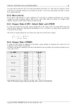
8.2.4
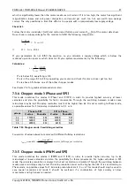
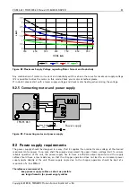
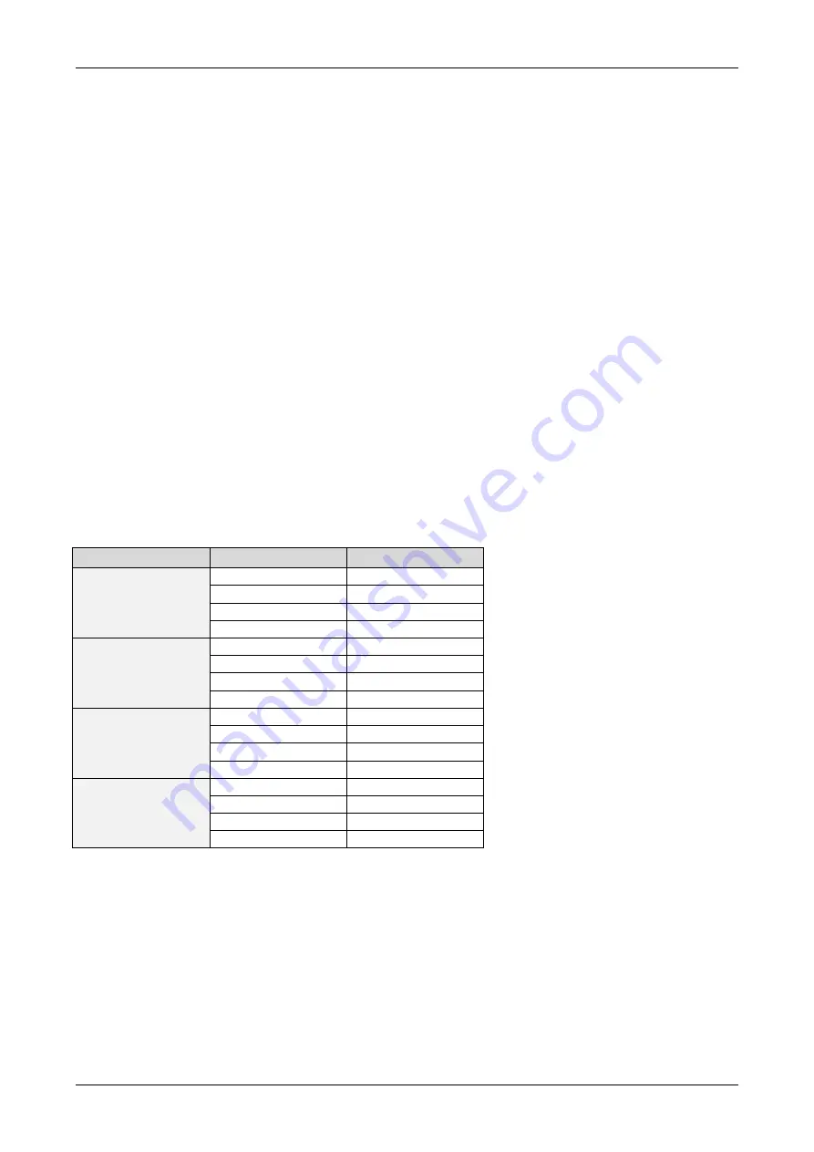
Chopper Mode 2 (PHASE)
In Table 8.1 and Figure 8.2 examples of maximum supply voltages V
S
regarding the current I
COIL
and
inductivity L of your motor are specified.
For further information, including a formula and description how to calculate the maximum voltage for your
setup, refer to 7.3.3.
I
COIL
(RMS)
L (min.)
V
S
(max.)
1000 mA
1.2 mH
24 V
0.9 mH
18 V
0.6 mH
12 V
0.35 mH
7 V
700 mA
1.7 mH
24 V
1.3 mH
18 V
0.9 mH
12 V
0.5 mH
7 V
500 mA
2.4 mH
24 V
1.8 mH
18 V
1.2 mH
12 V
0.7 mH
7 V
350 mA
3.4 mH
24 V
2.6 mH
18 V
1.7 mH
12 V
1.0 mH
7 V
Table 8.1: Maximum supply voltage regarding motor current and inductivity


