Trinamic PANdrive PD-1140 Hardware Manual Download Page 1


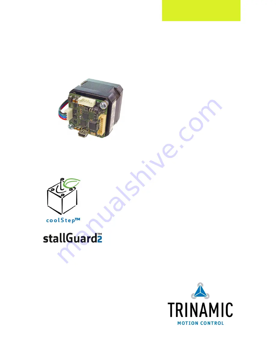
MECHATRONIC DRIVE WITH STEPPER MOTOR


                        PANdrive


TRINAMIC Motion Control GmbH & Co. KG 


Hamburg, Germany 
 

www.trinamic.com 


Hardware Version V1.2 

HARDWARE MANUAL 


+


+


PD-1140 


+    


U

NIQUE 

F

EATURES


Stepper Motor with  
Controller / Driver 

0.22 - 0.70


Nm / 24


V DC 

sensOstep

 Encoder 

USB, RS485, and CAN


Summary of Contents for PANdrive PD-1140

Page 1: ...OR PANdrive TRINAMIC Motion Control GmbH Co KG Hamburg Germany www trinamic com Hardware Version V1 2 HARDWARE MANUAL PD 1140 UNIQUE FEATURES Stepper Motor with Controller Driver 0 22 0 70 Nm 24 V DC sensOstep Encoder USB RS485 and CAN ...

Page 2: ...4 3 2 2 Analog Input IN_0 14 4 3 2 3 Outputs OUT_0 OUT_1 14 4 3 3 Motor Connector 15 4 3 4 Mini USB Connector 16 5 Reset to Factory Defaults 17 6 On Board LEDs 18 7 Operational Ratings 19 8 Torque Curves 20 8 1 1 PD42 1 1140 Torque Curve 20 8 1 2 PD42 2 1140 Torque Curve 20 8 1 3 PD42 3 1140 Torque Curve 21 8 1 4 PD42 4 1140 Torque Curve 21 9 Functional Description 22 10 PD 1140 Operational Descri...

Page 3: ...step High efficient operation low power dissipation Dynamic current control Integrated protection stallGuard2 feature for stall detection coolStep feature for reduced power consumption and heat dissipation Encoder sensOstep magnetic encoder 1024 increments per rotation e g for step loss detection under all operating conditions and positioning supervision Interfaces RS485 2 wire communication inter...

Page 4: ... 2 1 stallGuard2 load measurement SG as a function of load coolStep coolStep is a load adaptive automatic current scaling based on the load measurement via stallGuard2 adapting the required current to the load Energy consumption can be reduced by as much as 75 coolStep allows substantial energy savings especially for motors which see varying loads or operate at a high duty cycle Because a stepper ...

Page 5: ...tion PANdrive 0 44Nm max holding torque 42 x 42 x 60 PD42 4 1140 option PANdrive 0 70Nm max holding torque 42 x 42 x 73 Table 3 1 PD 1140 order codes The following options are available Firmware option Description Order code example TMCL Module pre programmed with TMCL firmware PD42 1 1140 TMCL Table 3 2 PD 1140 firmware options A cable loom set is available for this module Order code Description ...

Page 6: ...ensOstep technology and a NEMA17 bipolar stepper motor Currently there is a choice between four NEMA 17 42mm bipolar stepper motors with different lengths and different holding torques Length 42 1 2 22 0 05 24 1 20 5 4 5 13 max 37 22 42 1 42 1 5 42 1 34 2xM3 42 1 37 34 3 FRONT VIEW REAR VIEW Figure 4 1 PD 1140 dimensions Model Length of motor PD42 1 1140 33 5 1 mm PD42 2 1140 38 1 mm PD42 3 1140 4...

Page 7: ...r temperature C 80 80 80 80 Shaft radial play 450g load mm 0 02 0 02 0 02 0 02 Shaft axial play 450g load mm 0 08 0 08 0 08 0 08 Max radial force 20mm from front flange N 28 28 28 28 Max axial force N 10 10 10 10 Rated voltage VRATED V 2 0 2 4 2 4 4 4 Rated phase current IRMS RATED A 2 0 2 0 2 0 2 0 Phase resistance at 20 C RCOIL Ω 1 0 1 2 1 4 2 3 Phase inductance typ mH 1 6 2 2 2 1 6 0 Holding to...

Page 8: ...e I O 1 8 Power and Communication 1 6 Figure 4 2 Overview connectors Label Connector type Mating connector type Power and Communication Connector JST B6B PH K S JST PH series 6pins 2mm pitch Connector housing JST PHR 6 Contacts JST SPH 002T P0 5S Wire 0 22mm2 AWG 24 Multipurpose I O Connector JST B8B PH K S JST PH series 8pins 2mm pitch Connector housing JST PHR 8 Contacts JST SPH 002T P0 5S Wire ...

Page 9: ...hese are ceramic capacitors which have been selected for high reliability and long life time The module includes a 28V suppressor diode for over voltage protection There is no reverse polarity protection The module will short any reversed supply voltage due to the suppressor diode uni directional version and the internal diodes of the driver transistors It is important that the power supply voltag...

Page 10: ...on resistor Therefore 120 Ohm termination resistors at both ends of the bus have to be added externally 3 NUMBER OF NODES The RS485 electrical interface standard EIA 485 allows up to 32 nodes to be connected to a single bus The bus transceiver used on the PD 1140 units SN65HVD3082ED has just 1 8th of the standard bus load and allows a maximum of 256 units to be connected to a single RS485 bus 4 NO...

Page 11: ... of the bus c node 1 node n 1 node n Host Slave Slave Slave CAN termination resistor 120 Ohm termination resistor 120 Ohm keep distance as short as possible Figure 4 6 CAN bus structure 2 BUS TERMINATION Especially for longer busses and or multiple nodes connected to the bus and or high communication speeds the bus should be properly terminated at both ends The TMCM 1140 does not integrate any ter...

Page 12: ...B Input General purpose digital input 24V compatible Alternate function 1 right stop switch input Alternate function 2 external incremental encoder channel B input 8 IN_3 HOME ENC_N Input General purpose digital input 24V compatible Alternate function 1 home switch input Alternate function 2 external incremental encoder index zero channel input Table 4 4 Multipurpose I O connector Note All inputs ...

Page 13: ...puts on off The three digital inputs have alternate functionality depending on configuration in software The following functions are available Label pin Default function Alternate function 1 Alternate function 2 IN_1 6 General purpose digital input STOP_L left stop switch input connected to processor and TMC429 REF input supporting left stop functionality in hardware ENC_A external incremental enc...

Page 14: ...ltages below 0 V GND and above 3 3 V DC see figure below 3 3V IN_0 ADC input microcontroller 22k 10k 100nF GND GND GND Figure 4 8 General purpose inputs simplified input circuit 4 3 2 3 Outputs OUT_0 OUT_1 The eight pin connector of the TMCM 1140 offers two general purpose outputs OUT_0 and OUT_1 OUT_0 is an open drain output capable of switching up to 1A The output of the N channel MOSFET transis...

Page 15: ...s 2mm pitch single row connector is available The motor connector is used for connecting the four motor wires of the two motor coils of the bipolar stepper motor to the electronics 4 1 Pin Label Direction Description 1 OB2 Output Pin 2 of motor coil B 2 OB1 Output Pin 1 of motor coil B 3 OA2 Output Pin 2 of motor coil A 4 OA1 Output Pin 1 of motor coil A Table 4 5 Motor connector Example for conne...

Page 16: ...he module will accept commands via USB USB BUS POWERED OPERATION MODE The TMCM 1140 supports both USB self powered operation when an external power is supplied via the power supply connector and USB bus powered operation no external power supply via power supply connector On board digital core logic will be powered via USB in case no other supply is connected USB bus powered operation The digital ...

Page 17: ...he bottom side of the board have to be shortened Please perform the following steps 1 Power supply off and USB cable disconnected 2 Short two pads as marked in Figure 5 1 3 Power up board power via USB is sufficient for this purpose 4 Wait until the on board red and green LEDs start flashing fast this might take a while 5 Power off board disconnect USB cable 6 Remove short between pads 7 After swi...

Page 18: ... green LED should be flashing slowly during operation and the red LED should be off When there is no valid firmware programmed into the board or during firmware update the red and green LEDs are permanently on BEHAVIOR OF LEDS WITH STANDARD TMCL FIRMWARE Status Label Description Heartbeat Run This green LED flashes slowly during operation Error Error This red LED lights up if an error occurs Red L...

Page 19: ...COIL A TENV Environment temperature at rated current no forced cooling required Tbd 50 C Table 7 1 General operational ratings of module OPERATIONAL RATINGS OF MULTIPURPOSE I OS Symbol Parameter Min Typ Max Unit VOUT_0 Voltage at open drain output OUT_0 0 VDD V IOUT_0 Output sink current of open drain output OUT_0 1 A VOUT_1 Voltage at output OUT_1 when switched on 5 V IOUT_1 Output source current...

Page 20: ...24V 2A 256µsteps 8 1 2 PD42 2 1140 Torque Curve Figure 8 2 PD42 2 1140 torque vs velocity 24V 2A 256µsteps 0 00 0 05 0 10 0 15 0 20 0 25 0 30 10 100 1000 10000 torque Nm speed rpm PD42 1 1140 2A RMS Phase Current 256 uSteps 0 00 0 05 0 10 0 15 0 20 0 25 0 30 0 35 0 40 0 45 10 100 1000 10000 torque Nm speed rpm PD42 2 1140 2A RMS Phase Current 256 uSteps ...

Page 21: ...A 256µsteps 8 1 4 PD42 4 1140 Torque Curve Figure 8 4 PD42 4 1140 torque vs velocity 24V 2A 256µsteps 0 00 0 10 0 20 0 30 0 40 0 50 0 60 10 100 1000 10000 torque Nm speed rpm PD42 3 1140 2A RMS Phase Current 256 uSteps 0 00 0 10 0 20 0 30 0 40 0 50 0 60 0 70 0 80 10 100 1000 10000 torque Nm speed rpm PD42 4 1140 2A RMS Phase Current 256 uSteps ...

Page 22: ...the serial interfaces In Figure 9 1 the main parts of the PD 1140 are shown the microprocessor which runs the TMCL operating system connected to TMCL memory the motion controller which calculates ramps and speed profiles internally by hardware the power driver with stallGuard2 and its energy efficient coolStep feature the MOSFET driver stage the QSH stepper motor and the sensOstep encoder with res...

Page 23: ...on The higher the value is the less is the maximum acceleration default value 0 0 13 Usrs microstep resolution microsteps per fullstep 2usrs 0 8 a value of 7 or 8 is internally mapped to 6 by the TMC429 Table 10 1 TMC429 velocity parameters MICROSTEP FREQUENCY The microstep frequency of the stepper motor is calculated with 32 2048 2 _ div pulse CLK velocity Hz f Hz usf with usf microstep frequency...

Page 24: ... 1 usrs 6 Hz MHz msf 31 122070 32 2048 2 1000 16 1 Hz Hz fsf 34 1907 2 31 122070 6 s MHz Mhz a 21 119 2 1000 16 29 1 1 2 s MHz s MHz af 863 1 2 21 119 6 CALCULATION OF THE NUMBER OF ROTATIONS A stepper motor has e g 72 fullsteps per rotation 49 26 72 34 1907 rotation per fullsteps fsf RPS 46 1589 72 60 34 1907 60 rotation per fullsteps fsf RPM ...

Page 25: ...nd whose failure to perform when properly used in accordance with instructions provided can be reasonably expected to result in personal injury or death TRINAMIC Motion Control GmbH Co KG 2013 Information given in this data sheet is believed to be accurate and reliable However neither responsibility is assumed for the consequences of its use nor for any infringement of patents or other rights of t...

Page 26: ...6 SD Names of inputs changed AIN_0 IN_0 IN_0 IN_1 IN_1 IN_2 IN_2 IN_3 Names of outputs changed OUT_1 OUT_0 OUT_0 OUT_1 Table 12 1 Document revision 12 2Hardware Revision Version Date Description TMCM 1040_V10 2011 MAR 08 Initial version TMCM 1140_V11 2011 JUL 19 Optimization of multipurpose I O circuits Clock generation and distribution changed 16MHz oscillator TMCM 1140_V12 2012 APR 12 Further co...

Reviews: