


Gebrüder TRILETY Ges.m.b.H.
MCK-M31 1.02
09/ 2018
* Optional equipment
Page
15
4. Wind up the 4 sweeper unit support legs, so that the sweeper unit is in a
position that ensures that the vehicle can be driven underneath without
touching the sweeper unit.
5. Drive the vehicle underneath the sweeper unit and position the vehicle so
that the ball joints are underneath the ball joint receptacles.
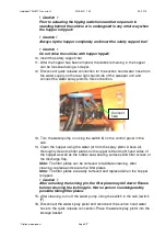
6. Connect the sweeper unit hopper tipping hydraulic hose connections to the
quick release couplings for the vehicle tipping cylinder.
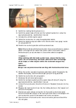
7. Evenly lower the sweeper body onto the vehicles ball joints by winding down
the 4 support legs. Ensure that all the ball joints are correctly inserted in the
receptacles. Insert the safety pins underneath the ball joints.
8. Remove the support legs from the holding tubes and store them.
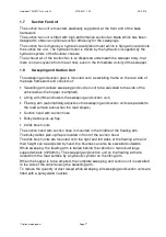
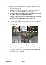
9. Connect the hydraulic hoses for the suction fan on to the connectors on the
right hand side behind the drivers cab.
10. Connect Leakoil.
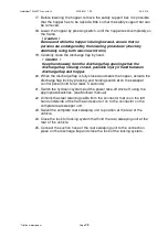
11. At the rear of the vehicle, connect the hydraulic hose quick release
connections according to the numbering (or description)
12. Connect the 7-pin electrical plug for the additional Road Traffic Licensing
Regulations lighting onto the socket on the rear of the vehicle.
13. Connect the electrical plug for the connecting cable onto the socket at the
rear of the vehicle or place the control panel into the cab through the rear
window (depending on the model).
Connect here
hydraulic-tube for
suction unit lifting
(coupling for tipping
cylinder)
leakoil


