


TI106 CDI Installation Manual
20 June 2019
02179-00
Issue AA
______________________
Page 4
Trig Avionics Europe B.V.
3. Pre-Installation
3.1 General Information
This section contains information and considerations required to prepare for the TI106 CDI installation, including
provided equipment, panel location, wiring and other information.
3.2 Unpacking and Inspecting Equipment
When unpacking this equipment, make a visual inspection for evidence of any damage that may have occurred
during shipment.
3.2.1
Materials Supplied
3.2.2
Materials not supplied
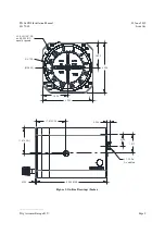
3.3 Equipment Location
The TI106 CDI should be mounted as close to the pilot’s field of view as possible.
Consideration should be given to the depth behind the panel where the unit will be installed. Clearance for the unit
as well as its electrical connections and routing must be allowed. Be aware of routing cables near other electronics
or with other wire bundles that may contain high energy flow. Examples of these sources could include 400 Hz AC
or COM, DME, HF and transponder transmitter coax.
Use of shielded wire may be useful in isolating the low-level signals that drive the CDI from other interference.
Avoid sharp bends in cabling and routing near aircraft control cables. Also, avoid proximity and contact with aircraft
structures, avionics equipment, heat sources or other obstructions that could chafe or damage wires during flight and
cause undesirable effects.
No direct cooling is required. As with any electronic equipment, overall reliability may be increased if the TI106 is
not located near any high heat source or crowded next to other equipment.
The TI106 CDI is designed primarily to be installed in the instrument panel of the aircraft. However, within the
limitations of the environmental qualifications, other locations may be acceptable when considered within the
context of the specific application and with the appropriate installation certification.
3.4 Cable Harness
Construct the cable harness in accordance with the guidance detailed in Section 3.4.1 using industry-accepted
practices regarding aircraft wiring and applicable regulatory requirements and guidance.
Refer to Section 3.3: Equipment Location for routing precautions.
Unit Description
Quantity
Trig Part Number
TI106 CDI
1
01913-00
TI106 Connector Kit
1
02121-00
Installation Manual
1
02179-00
Unit Description
Quantity
Specification
#6 UNC Screws
3
Max Length: 1.0”
Wire
As Required
22 AWG. (
See Section 3.4
)
Summary of Contents for TI106
Page 2: ...This page intentionally left blank ...
Page 4: ......


