


TI106 CDI Installation Manual
20 June 2019
02179-00
Issue AA
______________________
Page 8
Trig Avionics Europe B.V.
4. Installation
This section contains interconnect diagrams, mounting dimensions and other information pertaining to the
installation of the TI106 CDI. After installation of cabling and before installation of the equipment, ensure that
power is applied only to the pins specified in the interconnect diagram.
4.1 Mounting
Install the TI106 CDI within the aircraft in accordance with the aircraft manufacturer’s instructions and the
following steps:
1.
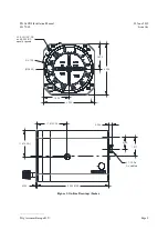
Verify that the instrument panel cut-out meets the requirements of Figure 2.
2.
Secure the indicator to the instrument panel using the proper mounting hardware.
3.
Connect the electrical connector(s) to the connector on the back of the unit.
Figure 2: Panel Cut-out (Inches)
4.2 Installation Completion
Prior to flight, verify the basic operation of the unit, interface with other equipment, lighting performance in various
conditions, and general expected performance.
Ø 3.156
2.480
TYP
1.240
TYP
Ø 0.156 (3X)
1.152
1.152
0.408
1.240 TYP
2.480 TYP
unit outline
(ref)
Summary of Contents for TI106
Page 2: ...This page intentionally left blank ...
Page 4: ......


