background image


  8


SELECTING PROPER DIES

Proper die selection is essential. Other than the obvious  

necessity of matching shaped punches and dies, there are 

two other basic selection factors that must be considered. 

The first is die clearance. Different material types and 

different material thicknesses require different clearances

between the punch and die. In order to maintain the best

possible hole while remaining within the tonnage 

capacity of the machine, it is essential to choose the die

with the proper clearance. The second is the die angle. 

Most structural shapes can be punched with the standard  


flat dies, but "I" -beams and most channels which 

have a 2-in-12 taper require the use of special 

9-1/2 degree angled dies. Car and ship channel 

flanges and other structural shapes with a 2 degree

taper can be punched with flat dies. Materials with

a flange taper of less than 5 degrees can also be 

punched with the flat die, however, the hole will be

slightly angled. Refer to specific information and

tables within this manual for the proper punch and

die combination. 


Hougen-Ogura Punches are 

designed to be used in 

Structural Steel. If used in harder 

or higher tensile strength 

materials, performance will be 

impeded and serious damaged 

could occur to your unit.

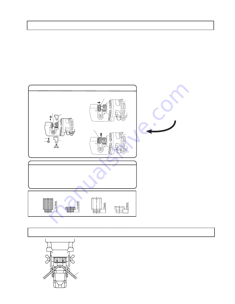
Your Hougen-Ogura punch unit 

has been equipped with a new 

die configuration. Please review 

this information prior to 

operating your machine


1. To make it easier, please remove the 
    strippers  


3.  Pull the die up to the tip of the punch

2. Unscrew the nuts and set screws
    that hold the die in place

4. Remove the die from the “C”- frame, 
    inclining it to remove. 

STRIPPER 

STRIPPER 

PUNCH

SET SCREW

NUT

                                        REMOVING THE NEW DIE


INSTALLING A PUNCH

1.  To make the operation easier, first remove the strippers on both sides.
2.  Reference your Operators manual and remove your punch and the die.
3.  Install a new punch and punch retaining nut.
4.  Install the die (Reference the steps above and work in reverse)
5.  Tighten the punch retaining nut according to the Instructions in your Operators manual. 

New Die 

Old Die 

CAUTION WHEN SELECTING THE DIE

It is important that the die selected is correct for the thickness of the material to 

be punched.

Punching material of thickness 4 mm to 8 mm using a die for thinner material 

can cause the punch to jam in the material. This is due to the smaller clearance 

betweenthe die and punch. In such a case the material will be pulled up by the 

retracting punch as shown in the drawing on the left. Special care should be 

taken when punching flat bar of mild steel, aluminum and copper.

Material

Summary of Contents for Hougen-Ogura PUNCH PRO 75004PR

Page 1: ...ELECTRO HYDRAULIC HOLE PUNCHER operator s manual COVERS HOLE PUNCHER PART NUMBERS 0754102 0754202 75004PR PUNCH PRO OM75004PR0815 Printed in U S A ...

Page 2: ...kly and efficiently Through constant innovation and development Hougen is committed to provide you with hole producing tools and products to help you be more productive Before attempting to operate your new hole puncher please read all instructions first These include the Operator s Manual and Warning Label on the unit itself With proper use care and maintenance your model will provide you with ye...

Page 3: ...ower cord Never carry battery charger by its power cord or pull on the cord to disconnect it Keep cord away from heat oil and sharp objects Place cord so that it will not be stepped on tripped over or otherwise subjected to damage or stress If the tool is dropped or struck check carefully that the body is not damaged cracked or deformed 14 Do not overreach Keep proper footing and balance at all ti...

Page 4: ...of its stroke The automatic valve remains open until the punch piston has fully returned to the home position As a result of this design the piston will not return to its home position automatically unless the full stroke has been completed Also the punch will not begin another stroke unless the punch has fully returned to the home position resetting the automatic valve In the event that the punch...

Page 5: ...the supplied hardware When using the stand periodically check to make sure that the punched material slugs are not stacking up between the exit hole in the C frame and the stand Keep this area clear of accumulated slugs USING THE WORK STAND TRIGGER SWITCH SLIDE STOPPER Pull the trigger switch for punching operation Make sure that the switch is fully depressed DO NOT ride the switch as this will ha...

Page 6: ...st and then the die Unscrew the punch retaining nut to remove the punch and remove the set bolt and the nut to remove the die Note When replacing the punch and the die make sure that the correct size thickness and hole shape is seleted Shaped punches and dies must be properly aligned with each other 3 Place the punch in the punch retaining nut then insert the punch with the nut into the punch pist...

Page 7: ...the punch piston 4 Make sure the punch is correctly positioned in the punch rod and tighten the punch retaining nut firmly with the Tommy Bar supplied 5 Place the die in the C frame in the proper orientation secure firmly with the set bolt and tighten the nut 6 Replace the strippers CAUTION Before replacing the punch and die ensure that the machine is disconnected from its power source to prevent ...

Page 8: ...s performance will be impeded and serious damaged could occur to your unit Your Hougen Ogura punch unit has been equipped with a new die configuration Please review this information prior to operating your machine 1 To make it easier please remove the strippers 3 Pull the die up to the tip of the punch 2 Unscrew the nuts and set screws that hold the die in place 4 Remove the die from the C frame i...

Page 9: ...and off to jog the punch down to the work piece If the position is not satisfactory open the manual return lever to retract the punch for another attempt If the punch doesn t return to its starting position with manual return lever open pull the trigger switch to return the punch CAUTION WHEN USING THE STRIPPER Do not position the material with one end or both ends unsupported by the stripper If t...

Page 10: ...t are clean so that no dirt dust or other foreign material can get into the hydraulic oil or pump area 1 Locate the socket head cap screw that plugs the oil port It is just above the manual return lever on the right hand side of the Hole Puncher 2 Lay the Hole Puncher on its left side so that the oil port is facing up 3 Turn on the switch to move the punch piston almost to the bottom of its stroke...

Page 11: ...og the punch down to the work surface If the position is not satisfactory open the manual return valve to retract the punch for another attempt This operation can also be performed with the manual return valve cracked open slightly to prevent full punching pressure from being developed In this manner the punch can be easily brought right down to the surface without beginning to punch the hole If t...

Page 12: ...12 PARTS BREAKDOWN ...

Page 13: ...ing 1 61 76426 Needle Holder B 1 Det Part Description Qty 62 76427 Needle Holder A 1 63 76428 Needle Bearing 1 64 76429 Stop Ring 1 65 76430 Pump Case 1 66 75090 Seal Washer 1 67 75107 Bolt HB10 x 15 1 68 75259 Oil Seal 1 69 75327 Ball Bearing 1 70 76468 Motor Flange 1 71 75835 Washer 4 72 76433 Bolt 4 73 75821 Armature Set 110V 1 set 76469 Armature Set 220V 1 set 74 75825 Rubber Pin 1 75 75822 In...

Page 14: ...915 5 64 078 to 3 8 375 14 to 3 GA F A H Die 23 32 SB 75916 3 4 750 19mm 76345 5 64 078 to 1 8 125 14 to 11 GA F A H Die 3 4 SA 76330 5 64 078 to 3 8 375 14 to 3 GA F A H Die 3 4 SB 76331 5 16 312 max C Die 3 4 C 75961 25 32 787 20mm 76346 5 64 078 to 1 8 125 14 to 11 GA F A H Die 25 32 SA 76332 5 64 078 to 3 8 375 14 to 3 GA F A H Die 25 32 SB 76333 5 16 312 max C Die 25 32 C 75962 OBLONG PUNCH M...

Page 15: ... R O T O M F O N O I T A T O R T I U C R I C R E W O P N E P O D R O C N O I S N E T X E G U L P K C E H C R E K A E R B T I U C R I C E G A T L O V R E P O R P M I E C R U O S R E W O P K C E H C P O R D E G A T L O V E V I S S E C X E F O E R A S D R O C N O I S N E T X E E H T R O F E Z I S E R I W T N E I C I F F U S N I D R O C E H T F O H T G N E L R O S D R O C D E G A M A D R O N R O W S E...

Page 16: ...ary from state to state To obtain warranty service return the item s transportation prepaid to your nearest Factory Authorized Repair Center or to Hougen Manufacturing Inc 3001 Hougen Drive Swartz Creek Michigan 48473 Hougen Drills Rotabroach Cutters are warranted against manufacturing defects only Subject to Hougen Manufacturing inspection THIS WARRANTY IS IN LIEU OF ANY OTHER WARRANTY EXPRESSED ...

Reviews: