background image

18

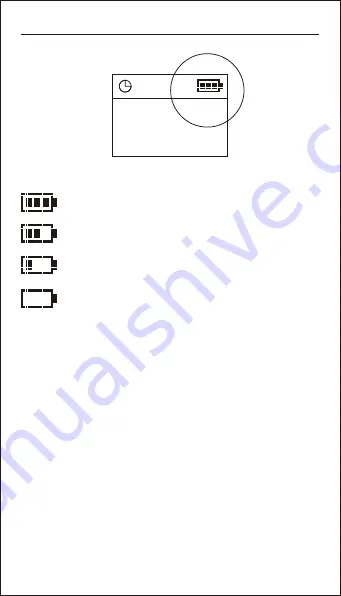
Batteries detecting and charging

Four levels indication of power detection

Represents the remaining 80%---100% electricity


Represents the remaining 40%---80% electricity


Represents the remaining 20%---40% electricity


Represents the remaining electricity less than 20%

     After connecting the USB charger, a charging icon shows on the

 screen. If there are rechargeable batteries in the device, it starts
 
chargingthe rechargeable batteries. Forbid using non-rechargeable 

batteries to charge, or it might lead to leakage, even burning.
   
    When the remaining electricity is less than 20%, you should promptly

shut down the device  and recharge it. Long time undervoltage will 

shorten the lifetime of the rechargeable batteries. When the charging is 

finished, the battery remaining indicator will stop flashing. The batteries

 has finished the fast recharge and can be used directly. If you do not stop

 recharging at this time, the device will continue the trickle charge state, 

using small current to supply natural discharge. But this process is not 

more than 24 hours. The device can still be used while charging.

Summary of Contents for AOF500

Page 1: ...USER S GUIDE PON Optical power meter English English...

Page 2: ......

Page 3: ...he drive If the temperature changes suddenly while using the drive Stop using it andtake out batteries forat least an hour Storage When long time no use must take out the batteries to avoid destroying...

Page 4: ...User s Guide Packet 2 PON Optical Power Meter 2s PERM VFL F P Mode ReCall Save REF Enter Threshold dBm dB USER S GUIDE Optical power meter Host Standard English English 5V Chargering Optional...

Page 5: ...M connector 1 ONT 1310nm connector 4 Display screen 5 F P mode PASS WRNG FAIL main menu button 6 VFL controlling button 7 Up button 8 Threshold selection menu and calibration menu button 9 Reference s...

Page 6: ...1 Pull the battery cover lock 2 Raise the battry cover 3 Installing the battery correctly 4 Push the battery cover and lock Installing the battery 4...

Page 7: ...ermanent On Press the Power key to turn on the device with auto power off After 10minutes no key pressed it will auto power off Press Power key for 2 seconds when turn on the device the auto power off...

Page 8: ...OPM or VFL as optional part can bebuilt in the PON meter Without OPM or VFL it will show NO After booting the metershows function selection menu Press Up buttonor Down button to switch functions Then...

Page 9: ...nter Threshold dBm dB Fiber Optical Splitter ONT OLT PON Optical Power Meter 2s PERM VFL F P Mode ReCall Save REF Enter Threshold dBm dB Fiber Optical Splitter ONT OLT Testing configuration diagram of...

Page 10: ...function it will show a testing interface on the screen PON power meter can measure uplink signal 1310nm downlink data signal 1490nm and downlink video signal 1550nm in the PON network at the same tim...

Page 11: ...asured data and pre setting threshold Then device can judge whether the the communication requirement or not Threshold setting is described in detail in the chapters followed Press button quickly netw...

Page 12: ...al loss Or it can be used in comparing with the pre setting standard power Button is used to setting or checking out the reference value Short pressit the screen will show REF and a pre setting dBm va...

Page 13: ...hreshold The threshold is set to quickly detect whether the result is in range or not and to confirm whether the network can be used or not The offset value is set to calibrate the regular attenuation...

Page 14: ...set 10 groups of thres hold information Whenstart quick judgment mode it will show thecurrent referring threshold number on the top of the display screen in the form of Tx When finish choosing thresho...

Page 15: ...User can do easycalibration as the followingsteps Press the key to thecalibration menu as thepicture 1 Press the key to movethe cursor 2 Press the key to increase thevalue 3 Press the key to decrease...

Page 16: ...on can browse records andshow the data number on the top of the screen Press this button for two seconds under current interface the number will be showed on the upper left of the screen and store the...

Page 17: ...dBm dB 15 PON optical power meter display unit The measured data will be display in dBm value and uW value Press button can switch display unit...

Page 18: ...850 1300 1310 1490 1550 1625nm Short press can check the saved references of six calibration wavelengths above mentioned Long press this button can save current value asa reference Device can store 1...

Page 19: ...RADIATION TO DIRECT OR SCATTERED RADIATION Twinkle VFL Visual Fault Locator VFL is used to seek the failure point in bare fiber and cables including rupture lager loss connector seeking and so on Pres...

Page 20: ...non rechargeable batteries to charge or it might lead to leakage even burning When the remaining electricity isless than 20 you should promptly shut down the device andrecharge it Long time undervolta...

Page 21: ...Auto power off Battery lifetime 1490nmDownlink test 1550nmDownlink test Spectrum passband Spectrum passband Max permitted input level Max permitted input level Accurate Linearity Inserting loss Optica...

Page 22: ...nm 850 1300 1310 1490 1550 1625nm 15mW 20mW Standard PON Optical powermeter Standard PON Optical powermeter 1mW VFL Standard PON Optical powermeter 10mW VFL Standard PON Optical powermeter 15mW VFL St...

Page 23: ......

Page 24: ...P N40331 Rev 1019...

Reviews: