background image

25

Model 212B Miter Mandrel Head for SP/FF

92-0738 : Rev. 980331

Parts List, Sleeve Assembly, Indicator (P/N 46-0128)

Item

Part

No.

No.

Description

Qty

1.

29-0102

BEARING, BALL

2

2.

35-0222

NUT, LONG

1

3.

46-0126

SLEEVE, OUTER

1

4.

46-0127

SLEEVE, INNER

1

Summary of Contents for BEVELMASTER 212B

Page 1: ...STOMER MESSAGE Inside Front Cover SAFETY PRECAUTIONS 3 GENERAL DESCRIPTION 6 SPECIFICATIONS 7 MAINTENANCE 9 OPERATION 11 DISASSEMBLY AND ASSEMBLY 20 ACCESSORIES 21 ILLUSTRATED PARTS BREAKDOWN 22 TOOL BIT RESHARPENING POLICY Inside Back Cover WARRANTY INFORMATION Inside Back Cover ...

Page 2: ...Copyright 1998 Proprietary property of TRI TOOL Inc No reproduction use or duplication of the information shown hereon is permitted without the express written consent of TRI TOOL Inc ...

Page 3: ...glasses Do not operate cutting tools without eye protection Dress properly Do not wear loose clothing or jewelry They can be caught in rotat ing and moving parts Avoid slippery floors or wear nonskid footwear If you have long hair wear protective hair covering to contain it WORK AREA Keep the work area clean Cluttered work areas and benches invite injuries Consider the work area environment Keep t...

Page 4: ...ut of all cutting fluids and water Hydraulic drives Observe proper procedures for electrically driven power sources Avoid damage to hydraulic lines Keep quick disconnects clean Grit contamination causes malfunctions Air tools Check the exhaust muffler Broken or damaged mufflers can restrict air flow or cause excessive noise Use air motors only with a filtered lubricated and regulated air supply Di...

Page 5: ...h they were designed Do not reach into rotating equipment Do not reach into the rotating head stock to clear chips to make adjustments or to check surface finish A machine designed to cut steel will not stop for a hand or an arm Handle chips with care Chips have very sharp edges and are hot Do not try to pull chips apart with are hands they are very tough Avoid unintentional starts Do not carry or...

Page 6: ... two distinct types of adjustments are easily performed Angular Offset Parallel Offset With the Angular Offset Adjustment the Mandrel Shaft can be precisely aligned with the work piece even though the ID of the work piece might be irregular or it may be adjusted up to 5 from the centerline in any direction desired to give a mitered prep The Parallel Offset adjustment accurately re centers the Mand...

Page 7: ...SP FF 92 0738 Rev 980331 SPECIFICATIONS Weight 20 lbs 9 kg Weight will vary with the Jackscrew size Pipe Holding Capacities Basic Pipe Size 6 pipe up to sch 120 through 24 pipe sch 30 and up Using Adapter Extension Plate Envelope Drawing ...

Page 8: ...8 TRI TOOL INC 92 0738 Rev 980331 Location Identifications ...

Page 9: ...y if they are well maintained Keep the Miter Mandrel Head clean Brush away any chips or other debris with a soft bristle brush Wipe the Miter Mandrel Head down with a lightly oiled rag Inspect the Miter Mandrel Head before each use Check for stripped threads burred worn or missing parts and replace when necessary Identification of various major parts ...

Page 10: ...the Gimbal Plate from the Mandrel Head Check the spherical bearing surface for burrs and other defects Do not reuse any parts that show evidence of cracking bending or over stressing Apply a very thin film of general purpose grease or anti seize to the spherical surface of the Gimbel Plate two or three drops of light oil on each of the four 4 Spherical Washers grease or anti seize to both sides of...

Page 11: ...t 8 Jackscrews are removable They are made of heat treated steel and have a slight spherical radius on the surface that contacts the work piece On most surfaces this provides for excellent holding power with virtually no marring of the work piece Three 3 lengths of Jackscrews and four 4 lengths of Spacers are provided Combinations of Spacers will extend the ID Range ...

Page 12: ...ed ID Ranges It mounts to the front of the miter mandrel head P N 21 0101 Turn the Jackscrews to a diameter slightly smaller than the bore of the work piece Before the Miter Mandrel Head is mounted on the work piece both the Angular Offset and the Parallel Offset Adjustments should be approximately centered ...

Page 13: ...turning the Draw Rod counterclockwise the mandrel Shaft Assembly can be removed from the Miter Mandrel Head NOTE To make the parallel Offset Adjustment all four 4 screws must be slightly loose Check the gap between the Gimbal Plate and the Mandrel Head to see that it is approximately even all around Angular Offset Adjustmnet Mandrel Shaft Asst and Draw Rod Locations ...

Page 14: ...t Screws must be used in conjunction with each other All Screws must be at least slightly loose to allow movement If the Mandrel shaft is to be drawn directly toward one screw the opposite screw must be loosened far enough to allow for the take up before the near screw is tightened Leave the Draw Nut slightly loose during and after the Angular Offset adjustment Check to see that the Adapter Plate ...

Page 15: ...he center NOTE To make the Parallel Offset adjustment All four 4 screws must be slightly loose Once the Adapter Plate Assembly has been roughly aligned and centered temporarily snug all of the Adjustment Screws and the Draw Nut Insert the Miter Mandrel Head into the work piece NOTE It is highly desirable to mount the Miter Mandrel head so that Angular Offset Pivot Point is on the same plane with t...

Page 16: ...es are to be used simply select the required hardware from the Indicator Kit to be used as a pointer The first adjustment to be made after mounting is always the Angular Offset NOTE Changing the Angular Offset will always change the Parallel Offset but changing the Parallel Offset will not change the Angular Offset To move the Adapter Plate Assembly in a given direction one 1 or two 2 Angular Offs...

Page 17: ...w tighten the Screws on the side of the Adapter Plate Assembly which you wish to move away from in order to push the Adapter Plate Assembly in a given direction NOTE Never exceed 30 ft lbs 41 N m of torque on the Parallel Offset Adjustment Screws Repeat the indicating procedure and the Parallel Offset adjusting procedure as many times as necessary to achieve the accuracy desired Once the accuracy ...

Page 18: ... Assembly and tighten the Draw Rod to 75 ft lbs 102 N m to 100 ft lbs 136 N m At this time the Miter Mandrel should feel absolutely tight and rigid Before installing the Model 212B BEVELMASTER be sure to read the Operator s Manual giving special attention to all safety cautions and warnings 212B Miter Mandrel Short Perch Tool Holder Extension Adapter In the case of a short perch mounting applicati...

Page 19: ...r then 16 pipe CAUTION Do not exceed 060 1 52 mm chip load to avoid damage to the tool The adapter No 27 0626 is used to accommodate short perch mounting in elbows with miter mandrel only for 16 pipe and under with load limitations Item Part No No Description Qty 1 27 0626 ADAPTER EXTENSION TOOL HOLDER 1 2 33 2123 SCREW SHOULDER 1 Short Perch Mounting 8 to 16 Elbow Miter Mandrel Tool Holder Extens...

Page 20: ...Shaft Assembly rearward Remove the Draw Nut the Adapter Plate Assembly and the Torque Plate Remove the four 4 Angular Offset Adjustment Screws and the four 4 Spherical Washers Remove the Gimbal Plate Remove the Jackscrews and Spacers from the Head Assembly Assembly of the Miter Mandrel Head Assembly is done in the reverse order of disassembling NOTE Read the Maintenance section prior to assembling...

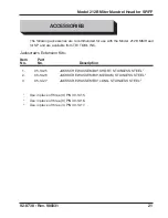
Page 21: ... and are available from TRI TOOL INC Jackscrews Extension Kits Item Part No No Description 1 05 1425 JACKSCREW ASSEMBLY SHORT STAINLESS STEEL1 2 05 1426 JACKSCREW ASSEMBLY MEDIUM STAINLESS STEEL2 3 05 1427 JACKSCREW ASSEMBLY LONG STAINLESS STEEL3 1 Use in place of three 3 P N 33 1415 2 Use in place of three 3 P N 33 1416 3 Use in place of three 3 P N 33 1417 ...

Page 22: ...22 TRI TOOL INC 92 0738 Rev 980331 MODEL 212B SP FF MITER MANDREL HEAD P N 06 0226 ILLUSTRATED PARTS BREAKDOWN ...

Page 23: ...R 1 5 29 0152 BEARING SPHERICAL WASHER 4 6 33 0557 SCREW SET 4 7 33 1321 SCREW HIGH TORQUE 4 8 33 1409 SCREW DRAW 1 9 34 0142 WASHER FLAT 75 ID 1 10 35 0076 NUT DRAW 1 11 33 1415 JACKSCREW 1 8 33 1416 JACKSCREW 2 8 33 1417 JACKSCREW 3 8 12 44 0217 SPACER 1 8 44 0218 SPACER 2 8 44 0219 SPACER 3 8 44 0220 SPACER 4 8 NOT SHOWN 86 0087 CASE 1 05 1174 WRENCH KIT 1 36 0010 WRENCH L 1 4 HEX 36 0059 WRENC...

Page 24: ...24 TRI TOOL INC 92 0738 Rev 980331 INDICATOR SLEEVE ASSEMBLY P N 46 0128 ...

Page 25: ...r Mandrel Head for SP FF 92 0738 Rev 980331 Parts List Sleeve Assembly Indicator P N 46 0128 Item Part No No Description Qty 1 29 0102 BEARING BALL 2 2 35 0222 NUT LONG 1 3 46 0126 SLEEVE OUTER 1 4 46 0127 SLEEVE INNER 1 ...

Page 26: ...26 TRI TOOL INC 92 0738 Rev 980331 DIAL INDICATOR ASSEMBLY P N 50 0015 ...

Page 27: ...List Dial Indicator Assembly P N 50 0015 Item Part No No Description Qty 1 30 0334 BASE MAGNETIC 1 2 30 0335 POST UPRIGHT 1 3 30 0336 SLEEVE 1 4 30 0337 ROD 1 5 30 0338 SLEEVE 1 6 30 0339 ATTACHMENT INDICATOR 1 7 30 0340 INDICATOR DIAL 1 8 30 0341 ATTACHMENT UNIVERSAL 1 ...

Page 28: ...738 Rev 980331 EXTENSION PLATE KIT P N 05 1219 Parts List Extension Plate Kit P N 05 1219 Item Part No No Description Qty 1 24 0608 EXTENSION PLATE 1 2 33 1456 SCREW CAP 1 2 20 X 1 75 4 NOT SHOWN 36 0012 WRENCH L 3 8 HEX 1 ...

Reviews: