tres900
Operations Manual
Revision G
www.tresrfsolutions.com
Transponder and Reader Engineered Systems, Inc
2142 O’Neal Lane Suite 354
▪
Baton Rouge, LA 70816
▪
888.574.tres (8737)
Page 13
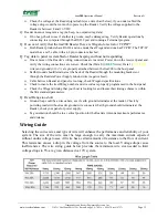
Check the voltage at the Reader pigtail cable (see wire chart below), if you under cabled the
voltage drop would be too much to power up the Reader. Verify the voltage supplied to the
Reader is between 8 and 16 VDC
Q: Reader does not recognize a tag (no beep, no outputted tag data)
If no beep, check to see if another tag works, maybe damaged tag. Verify Reader operations by
connecting to a computer through the RS232 port and running a Terminal program.
Q: How can I verify that the tres900 Reader I have is Wiegand or serial or TCP/IP?
Both Reader products have RS232 and one model has Wiegand and one has TCP/IP. The TCP/IP
model has a cat 5 cable with an 8 pin connector attached.
Q: Tag data to panel is scrambled or Reader beeping and host not responding
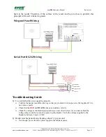
One or more of the Reader’s wiring connections are incorrect. Power down the receiver/panel and
verify the wiring connections are correct. Check that Data 0 (
GREEN
wire), Data 1 (
YELLOW
wire) and ground (
GRAY
) are properly attached between the tres900 to the host panel.
Earth Ground should terminate at the back of the Reader through the mounting brackets or
through the Readers Power Supply Ground wire (negative feed).
Cable between Reader and panel is too long, check Wiegand specifications
Check to insure the tres900 tag number and site code are properly programmed in the host panel.
Check the Wiegand timing that your host is looking for and insure their timing scheme is within
the SIA standard parameters.
Q: Read Range too short
Ground loop could be an issue here, see if earth ground terminates at the reader. Check by
powering reader without reader ground wire connected. Earth ground should terminate at the
Reader, check your panel or power supply.
Tag orientation should be in a vertical position for the Readers Antenna maximum performance
and distance.
Wiring
Guide
Selecting the correct size and type of wire will enhance the performance and reliability of your
system. The size of the wire must be large enough to carry the maximum current expected
without undue voltage losses. All wire has a certain amount of resistance to the flow of current.
This resistance causes a drop in the voltage from the source to the load. Voltage drops cause
inefficiencies. The wire sizing guide below provides the minimum wire size needed to limit
voltage drops to 5% at a given distance in a 12V system.

