tres900
Operations Manual
Revision G
www.tresrfsolutions.com
Transponder and Reader Engineered Systems, Inc
2142 O’Neal Lane Suite 354
▪
Baton Rouge, LA 70816
▪
888.574.tres (8737)
Page 11
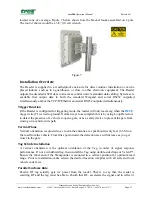
toward zone of coverage. Figure 7 below shows how the bracket looks assembled on a pole.
The tool of choice would be a 3/8” (10 cm) wrench.
Figure 7
Installation
Overview
The Reader is supplied in a weatherproof enclosure for direct outdoor installation or can be
placed indoors, such as in a guardhouse, or close to other electronic equipment. The Reader
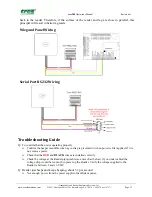
outputs the decoded ASCII data to an access control unit via standard data cabling. Systems are
available that output data in both the standard Wiegand and serial RS232 outputted
simultaneously and/or the TCP/IP Ethernet and serial RS232 outputted simultaneously.
Trigger
Function
If the Reader is configured for triggering mode, the reader will only read a tag when the
BLUE
trigger wire (T1) is tied to ground. Normal ways to accomplish this is by using Loop Detectors
to detect the presence of a vehicle to open a gate, or as a safety device to prevent the gate from
closing on a vehicle in its path.
Vertical
Plane
Vertical orientation is adjusted so as to aim the antenna at a spot about twenty feet (6.5 M) on
the road from the vehicle. From this spot forward, the detection area will increase as you get
closer to the gate.
Tag
Vehicle
Installation
A vertical orientation is the optimal orientation of the Tag in order of signal response
performance. If not a windshield tag, then install the Tag using double-sided tape or Velcro™.
Ensure the label-end of the Transponder is mounted in a vertical position for optimum read
range. Prior to installation, make certain the desired location complies with all state and local
vehicle code laws.
Parallel
Surfaces
Rule
Passive RF tag actually gets its’ power from the reader. That is to say that, the reader is
emitting RF and the tag must be able to absorb that RF, accelerate the signal and to reflect it

