background image


6


??

Install the Switch on a sturdy, level surface that can support 
its weight, or on a 19” EIA standard -size equipment rack.  
For information on rack installation, please see the next 
section, 

Rack  Mounting.


??

When installing the Switch on a level surface, attach the 
rubber feet on the corners at the bottom of the Switch. The 
rubber feet cushion the Switch and protect the bottom of the 
Switch. 


100Base-FX Module Installation 

The installation procedure for each module  is the same. Additional 
information about each module is provided in the module’s package. 


1.  Power off the switch. 

2.  Locate the module slot at the switch’s rear panel. 

3. 

Using a screwdriver, undo the two screws and remove the dust 
cover on the module slot. 

Note: reinstall the dusk cover when the 

slot is empty. 

4.  Holding the module  with the component-side up and connector-

side  going into the slot. Gently slide the module along the guides 
in the slot and firmly seat it in the internal connector. 

5.  Using a screwdriver, replace the two screws and tighten them 

until snug. 

Note: 

1. If the module is not present in the module bay, we recommend 
you install the dust cover over the module bay. 

Summary of Contents for TE100-S16plus

Page 1: ...TE100 S16plus 16 Port 10 100Mbps NWay Fast Ethernet Switch User s Guide ...

Page 2: ......

Page 3: ...and can radiate radio frequency energy and if not installed and used in accordance with this user s guide may cause harmful interference to radio communications Operation of this equipment in a residential area is likely to cause harmful interference in which case the user will be required to correct the interference at his own expense CE Mark Warning This is a Class A product In a domestic enviro...

Page 4: ......

Page 5: ...HIS USER S GUIDE III INTRODUCTION 1 FAST ETHERNET TECHNOLOGY 1 SWITCHING TECHNOLOGY 2 FEATURES 3 UNPACKING AND INSTALLATION 5 UNPACKING 5 INSTALLATION 5 100BASE FX MODULE INSTALLATION 6 RACK MOUNTING 7 IDENTIFYING EXTERNAL COMPONENTS 15 FRONT PANEL 15 REAR PANEL 16 LED INDICATORS 17 ...

Page 6: ...BASE TX Hub 23 HUB WITHOUT UPLINK MDI II PORT 23 A Using straight through cable 23 B Using crossover cable 24 SWITCH TO SWITCH OTHER DEVICES 24 A Using straight through cable 24 B Using crossover cable 24 PORT SPEED DUPLEX MODE 25 TECHNICAL SPECIFICATIONS 19 RJ 45 PIN SPECIFICATION 21 ...

Page 7: ...letter lower case refers to other Ethernet switches Overview of this User s Guide Introduction Describes the Switch and its features Unpacking and Installation Helps you get started with the basic installation of the Switch Identifying External Components Describes the front panel rear panel and LED indicators of the Switch Connecting the Switch Tells how you can connect the Switch to your Etherne...

Page 8: ......

Page 9: ... non disruptive smooth evolution from the current 10BASE T technology The non disruptive and smooth evolution nature and the dominating potential market base virtually guarantee cost effective and high performance Fast Ethernet solutions in the years to come 100Mbps Fast Ethernet is a new standard specified by the IEEE 802 3 LAN committee It is an extension of the 10Mbps Ethernet standard with the...

Page 10: ...ment to destination segment without interfering with any other segments By doing this the total network capacity is multiplied while still maintaining the same network cabling and adapter cards For Fast Ethernet networks a switch is an effective way of eliminating problems of uplinking Fast Ethernet hubs beyond the two repeater limit A switch can be used to split parts of the network into differen...

Page 11: ... speed servers With the highest bandwidth at 200Mbps 100Mbps full duplex mode each port can provide workstation with congestion free data pipe for simultaneous access to the server The Switch is expandable by cascading two or more switches together As all ports support 200Mbps the Switch can be cascaded from any port and to any number of switches The Switch is a perfect choice for 10Mbps network s...

Page 12: ... 100Mbps thereby providing you with automatic and flexible solutions for your network IEEE 802 3x flow control for full duplex mode operation Back pressure flow control for half duplex mode operation Data Forwarding Rate per port at wire speed for both 10Mbps and 100Mbps speed Data Filtering Rate per port at wire speed for both 10Mbps and 100Mbps speed eliminates all error packets runts etc 16K ac...

Page 13: ...two mounting brackets This User s Guide If any item is found missing or damaged please contact your local reseller for replacement Installation The site where you install the Switch may greatly affect its performance When installing consider the following pointers Install the Switch in a fairly cool and dry place See Technical Specification for the acceptable operating temperature and humidity ran...

Page 14: ...me Additional information about each module is provided in the module s package 1 Power off the switch 2 Locate the module slot at the switch s rear panel 3 Using a screwdriver undo the two screws and remove the dust cover on the module slot Note reinstall the dusk cover when the slot is empty 4 Holding the module with the component side up and connector side going into the slot Gently slide the m...

Page 15: ...ck Mounting The switch can be mounted in an EIA standard size 19 inch rack which can be placed in a wiring closet with other equipment Attach the mounting brackets at the switch s side panels one on each side and secure them with the provided screws After that use screws provided with the equipment rack to mount each switch in the rack ...

Page 16: ......

Page 17: ...for detailed information about each LED indicator Twisted Pair Ports Use any of these ports to connect network devices workstations hubs switches etc to the Switch These ports are MDI X ports and you can use ordinary straight through twisted pair cables to connect PCs workstations and Servers to the Switch If you need to connect these ports to devices with MDI X ports you need to use crossover cab...

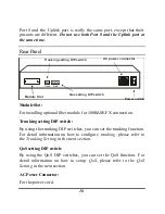
Page 18: ... For installing optional fiber module for 100BASE FX connection Trunking setting DIP switch By using the trunking DIP switches you can set the trunking function For detail information on how to configure trunking please refer to the Trunking Setting in the next section QoS setting DIP switch By using the QoS DIP switches you can set the QoS function For detail information on how to setup QoS pleas...

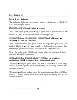
Page 19: ... port is in full duplex FDX mode It remains off for half duplex operation This LED blinks green when collision occurs on the respective port Note the full duplex LED lights green when the connected device supports full duplex operation 10M Link ACT and 100M Link ACT 10Mbps Link Activity amber and 100Mbps Link Activity green Indicator This indicator lights green when the port is connected to a 100M...

Page 20: ...le and diagrams below for more information You can select to trunk two Switches using 2 3 or 4 ports with Trunk Group A or B Please follow the instructions below to set the trunking dipswitches Note You can only trunk same model Switches together 1 Power off the Switch 2 Follow the table above to select the trunk ports and set the dipswitches 3 Repeat step 1 2 and configure another Switch A0 A1 Tr...

Page 21: ...19 4 Connect the trunk ports together using crossover CAT5 UTP STP cables 5 Power on the Switches Below are some trunking examples ...

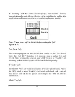
Page 22: ...of QoS multimedia applications such as Streaming Video and Network Conference can be sluggish or stopped due to network congestions This Switch supports leading edge QoS with three levels of priority settings The priority can be checked via layer 2 IEEE802 1Q VLAN Tagging and or layer 3 IP Header TOS bits Port Based Priority is also provided for user to set traffic prioritization according to the ...

Page 23: ...before setting the QoS dipswitches Port Based QoS There are eight ports on this Switch that can be set for Port Based QoS The QoS DIP Switches 1 8 represent port number 3 6 and 11 14 After setting the selected port s DIP Switch to Enable all incoming packets to these ports will be handled with priority IP Header QoS The QoS DIP Switch 9 enables disables IP header QoS feature When the DIP Switch is...

Page 24: ... Category 3 4 5 UTP STP straight cables The PC equipped with a RJ 45 10 100Mbps phone jack should be connected to any of the 16 ports 1x 16x Note Use CAT5 or better cable for 100Mbps connection After the connection is made the port LED on the Switch will show the status of the connection If LED indicator does not light after making a proper connection check the PC LAN card the cable the Switch and...

Page 25: ...T hub the Switch LED indicators should light up as the following FDX COL LED indicator is OFF LINK ACT LED indicator lights amber B 100BASE TX Hub When connecting to a 100BASE TX hub the Switch LED indicator should light up as the following FDX COL LED indicator is OFF LINK ACT LED indicator lights green Hub without Uplink MDI II port If a hub is not equipped with an uplink MDI II port connection ...

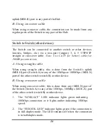
Page 26: ...t cable When using straight cable this is done from the Switch s uplink MDI II port Switch A to any of the 10Mbps or 100Mbps MDI X port of the other switch switch B or other device B Using crossover cable When using crossover cable this is done from any MDI X port of the Switch Switch A to any of the 10Mbps 100Mbps MDI X port of the other switch switch B or other device 1 The LINK ACT LED indicato...

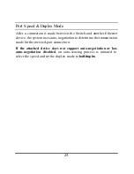
Page 27: ... device the system uses auto negotiation to determine the transmission mode for this twisted pair connection If the attached device does not support auto negotiation or has auto negotiation disabled an auto sensing process is initiated to select the speed and set the duplex mode to half duplex ...

Page 28: ......

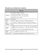
Page 29: ...fer Rate Ethernet 10Mbps half duplex 20Mbps full duplex Fast Ethernet 100Mbps half duplex 200Mbps full duplex Topology Star Network Cables 10BASET 2 pair UTP Cat 3 4 5 EIA TIA 568 100 ohm STP 100BASE TX 2 pair UTP Cat 5 EIA TIA 568 100 ohm STP 100BASE FX 62 5 125 micron multimode fiber optic Number of Ports 16 x 10 100Mbps NWay MDI X ports Uplink Port 1 x 10 100Mbps NWay MDI II port shared with po...

Page 30: ...midity Operating 10 90 Storage 5 90 Dimensions 440 x 140 x 44 mm W x H x D EMI FCC Class A CE Mark Class A VCCI Class A Performance Transmits Method Store and forward RAM Buffer 512KBytes per device Filtering Address Table 16K entries per device Packet Filtering Forwar ding Rate 10Mbps Ethernet 14 880 pps 100Mbps Fast Ethernet 148 800 pps MAC Address Learning Automatic update ...

Page 31: ... The following diagram and tables show the standard RJ 45 receptacle connector and their pin assignments for the switch to network adapter card connection and the straight crossover cable for the Switch to switch hub bridge connection RJ 45 Connector pin assignment Contact Media Direct Interface Signal 1 TX transmit 2 TX transmit 3 Rx receive 4 Not used 5 Not used 6 Rx receive 7 Not used 8 Not use...

Page 32: ...er cable connections MDI II uplink port to MDI X port connection using Straight Cable for connecting from Switch to switch or from Switch to other network device MDI X port to MDI X port connection using Straight Cable for connecting from Switch to switch or from Switch to other network device ...

Reviews: